
Digi International
Digi
One RealPort IA and PortServer TS 2/4 Configuration
for
Pass-Through
Modbus Multi-Master Communication
Table
of Contents
6.1.1.
Setting the Network Configuration
6.1.2.
Setting the IA Engine
Configuration
Index of Figures
Figure 1 - Targeted Hardware
Configuration
Figure
2- MEI DIP Switches set for RS-422/485 4-wire full-duplex
Figure
5 - IA Wizard - Serial Port 1 Configuration
Figure
6 - IA Wizard - Serial Port 1 IA Protocol Selection
Figure
7 - IA Wizard - Serial Port 1 IA Type Selection
Figure
8 - IA Wizard - Serial Port 1 Configuration Confirmation
Figure
9 - IA Wizard - Serial Port 2 Type Master
Figure
10 - IA Wizard - Serial Slave Protocol Configuration
Figure
11 - IA Wizard - Protocol Address Filtering
Figure
14 - MEI DIP Switches set for RS-232
Figure
15 - MEI DIP Switches set for RS-422/485 4-wire full-duplex
Figure
16 - MEI DIP Switches set for RS-485 2-wire half-duplex – termination enabled
(switch 4)
Index of
Tables
Table 1 - Terms and
Definitions
This document describes, in detail the steps required to get the Digi One TS 2 (henceforth referred to as the ‘TS2’) configured to allow a serial master device and one or more network master devices to communicate with a single serial slave.
This document shall provide, in detail, all of the steps required in order to get the Modbus equipment shown in Figure 1 communicating with each other.
Figure
1 -
Targeted Hardware Configuration
The equipment being referenced in this document is manufactured by Schneider-Electric. Nonetheless, the basic configuration will be the same no matter what Modbus device(s) are used.
This document describes a specific scenario in which access to the PLC on Port 1 of the TS2 is enabled from either the HMI connected to port 2 of the unit or via Ethernet (Modbus/TCP).
Once configured this scenario
allows for a Kepware OPC server to connect to the PLC via Modbus/TCP, while
simultaneously allowing a Magelis HMI, connected to port 2, to communicate with
the same PLC, on port 1. In fact,
multiple devices/systems could connect to the TS2 via Ethernet and access the
PLC, which is essentially the same thing that the Magelis was doing.
The following is a list of documents that have either been referenced within this document or could prove useful for any person using this document to configure a similar scenario.
· Command Reference
· Configuration and Administration Guide
· Setup Guide
The above documents are all available via the Support web page at http://support.digi.com, under the ‘Product Documentation’.
|
Term |
Definition |
|
TS2 |
Shortened form of the product name ‘Digi One TS 2’ |
|
EOS |
Acronym for Embedded Operating System. The ‘firmware’ running inside the TS2. |
|
IA |
Acronym for ‘Industrial Automation’ |
|
CLI |
Command Line Interface |
Table 1 - Terms and Definitions
The following is a list of the equipment used to assemble the scenario described in this document.
- 1 Digi One TS 2 (running 82000747_G version of the EOS)
- 2 TSX Momentum PLC’s
o Each TSX Momentum has a RS-485 (4-wire) serial interface as well as an Ethernet interface.
- 1 XBTH012010 Magelis HMI Display
o The Magelis has a RS-232 serial port.
- Appropriate serial and Ethernet cabling for each of the devices listed above.
This document describes the use of Modbus equipment that is in the possession of the Systems Assurance department. This equipment is referenced so as to provide a hard concise description of the proper configuration steps. These instructions can be applied to any Modbus scenario of a similar style. Likewise, these instructions would also apply to the configuration of a TS2, with slight modifications for the additional two serial ports on the device.
The configuration of the TS2 may be set by either the CLI or HTTP (web) interface. For the purposes of this document only the HTTP interface will be covered.
The factory default settings on the Ethernet interface attempts to (in this sequence) obtain its network configuration via DHCP followed by RARP. If both of these attempts fail, the IP address of the unit will be set to 0.0.0.0. The ‘Digi Device and Terminal Server Setup’ utility can be used to configure the Ethernet interface. This program is included on the CD-ROM shipped with the product. In addition the ‘Ping-ARP’ method can be utilized as well. This method is described in the documentation on the CD-ROM.
All of the port configuration parameters, e.g. flow control, parity, etc., can be configured either through the ‘Industrial Protocols’ Wizard or the ‘Configure’, ‘Ports’ menu selection. For the purposes of this document the ‘Industrial Protocols’ Wizard method will be followed.
The TSX Momentum PLC that is to be used as a Modbus serial slave has a RS-485 (4-wire) serial port on it. This means that it will have to be connected to the TS2 via port 1, as this is the only port that is capable of being configured as such. To configure port 1 for RS-485 turn the TS2 upside-down and position the bank of switches as follows:
|
|
1 |
2 |
3 |
4 |
|
ON |
|
|
|
|
|
OFF |
|
|
|
|
Figure 2- MEI DIP Switches set for RS-422/485 4-wire full-duplex
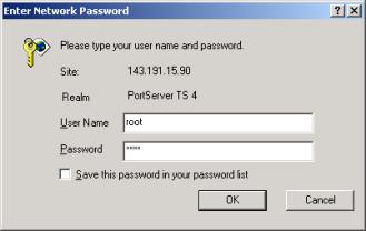
1. Launch your web browser of choice, Microsoft’s Internet Explorer will be used here, but any browser, i.e. Netscape, Opera, etc., should work.
2. Once connected to the TS2 log in using ‘root’ as the username and ‘dbps’ for the password.
3. On the left-hand side of the browser window is a menu, click on ‘Setup Wizards’ and then ‘Industrial Protocols’. Click Next.
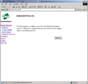
4. Each subsequent screen will contain some text describing what is to be done, possibly some drop-down lists and text fields allowing for the entry/selection of configuration information. After each step is completed, the ‘Next >>’ button should be clicked. Once the wizard gets past the first screen ‘Cancel’ and ‘<< Previous’ buttons will also be available. Unless otherwise stated, click the ‘Next >>’ button at the end of each step listed hereafter.
5. The first screen simply describes the purpose of the setup wizard.
6. Select the port to be configured. To begin with select ‘1’.
7. Using the drop-down lists, select the baud rate, data bits, parity and stop bits necessary for the device to be attached to port 1. For our configuration use the settings below:
a. Baud rate: 9600
b. Data bits: 8
c. Parity: Even
d. Stop bits: 1
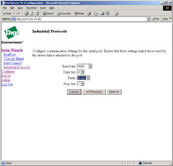
Figure 5 - IA Wizard - Serial Port 1 Configuration
8. Select the IA serial protocol desired; in our case we want ‘Modbus RTU’.
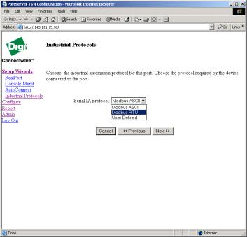
Figure 6 - IA Wizard - Serial Port 1 IA Protocol Selection
9. Since port 1 is the only port capable of RS-485 (4-wire) communication, the PLC will be attached to port 1 on the TS2. This PLC is going to be our Modbus serial slave, so select Slave.
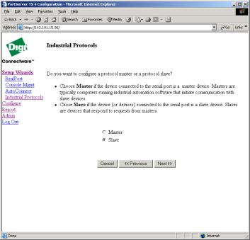
Figure 7 - IA Wizard - Serial Port 1 IA Type Selection
10. Review your selections for accuracy, making use of the ‘<< Previous’ and ‘Next >>’ buttons. Click the ‘Finish’ button when satisfied with the configuration.
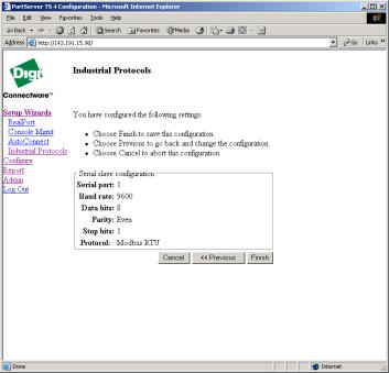
Figure 8 - IA Wizard - Serial Port 1 Configuration Confirmation
11. Following the information on the screen, choose menu item to configure port 2. Select port 2 as the serial port to configure. Repeat steps 7 and 8.
12. Since port 2 is to be connected to the Magelis HMI, it must be configured to be a Master.
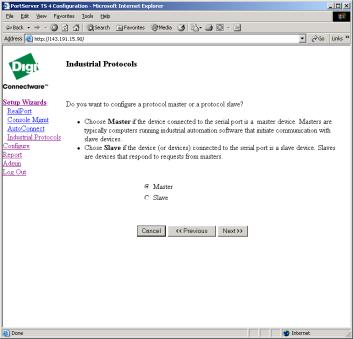
Figure 9 - IA Wizard - Serial Port 2 Type Master
13. When configured as a Master, the IA routing engine is enabled. This ‘engine’ allows one to specify which serial slave or network slave to send a Modbus packet to, based on the destination unit ID number (node number). Click ‘Next>>’ to configure IA route destinations. Click Next at the end of each of the following steps, unless specified otherwise.
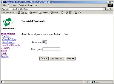
14. First we shall configure the route from port 2 to port 1, which is a Serial Slave. Select ‘Serial Slave’.
15. Select the serial port to be used as the destination slave. For our setup we will select port ‘1’. A description can be entered in the appropriate text box, as well, but is not necessary.
16. Select the IA serial protocol required, which is Modbus RTU in our setup.
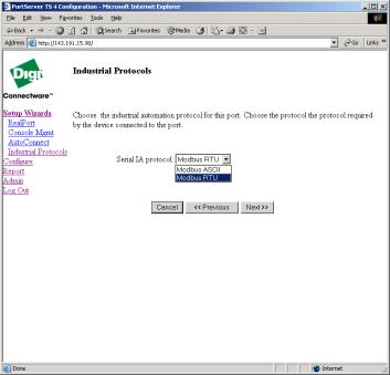
Figure 10 - IA Wizard - Serial Slave Protocol Configuration
17. For optimal performance the Protocol address filtering option can be setup to allow only a specific range of Modbus unit ID’s (node numbers) to be routed to this slave. However, it is advisable that the default of ‘Allow all protocol addresses’ be enabled initially. This will allow all ID’s from 0-255 to be routed to this slave. Once communication has been established and everything works as desired it may is possible to narrow this range down to a single unit ID.
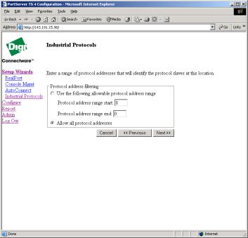
Figure 11 - IA Wizard - Protocol Address Filtering
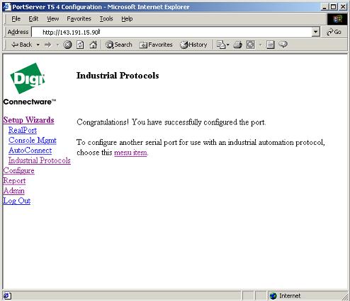
18. We are now given the opportunity to configure another route or finish with the wizard. Select the option for ‘No, finish the wizard’.
19. Review the configuration selections you have made and when satisfied click ‘Finish’
20.
This is the end of the Digi One TS 2 configuration.
The TS2 and TS4 provide multi-electrical interface (MEI) support on port 1 only. Ports 2-4 supports RS-232 only.
|
|
1 |
2 |
3 |
4 |
|
ON |
|
|
|
|
|
OFF |
|
|
|
|
Figure 12 - MEI DIP Switches set for RS-232
|
|
1 |
2 |
3 |
4 |
|
ON |
|
|
|
|
|
OFF |
|
|
|
|
Figure 13 - MEI DIP Switches set for RS-422/485 4-wire full-duplex
|
|
1 |
2 |
3 |
4 |
|
ON |
|
|
|
|
|
OFF |
|
|
|
|
Figure 14 - MEI DIP Switches set for RS-485 2-wire half-duplex – termination enabled (switch 4)