
| Products | |
| |
|
| • | device servers |
| • | terminal servers |
| • | console management |
| • | USB |
| • | async |

|
Digi (Central Data) PCI-4/8 Product Support
 PCI-4 |  PCI-8 |
Table of Contents
Cabling InformationWindows NT
Irix
Solaris 2
HP-UX
AIX 4
Note: This product has been discontinued, but will eventually be replaced by a better product designed at the MN site. We will are in the process of working on some of the drivers now. Send email to Greg_Helmkin (Product Manager) for updates.
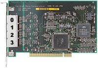
A note about which port is which on our PCI-4:
The PCI 4/8 backpanels don't have the ports numbered, which
was an oversight. Due to current circumstances, this will
probably not be changed. So, for the record, the first
port on the card is the port farthest away from the card
edge connector, or the port closest to the screw which holds
the backplate in place in the system (as shown above in the
picture).
Cabling Information
!! Important note on RJ-45 pinouts and adapters !!
The PCI-4/8 RJ-45 (8pin) pinout is NOT compatible with the pinout of the RJ-45 (usually 10pin) connectors on all other Digi products. You MUST get or make the correct adapter (shown below) for this product to work as expected. Pre-configured adapters are available via Digi Sales (same adapters as the SCSI/EtherLite products), but you must be sure to specify the correct ones.Our DB-25 connector:
We use the standard DTE pinout for the DB-25 connector, but we use female connectors to avoid possible pin shorts via pens or paper clips and such.
                              +--------------------------+
                              | pin | signal | direction |
      Female DB-25 DTE        |--------------------------|
                              |  2  |  TxD   |    out    |
        ___________           |  3  |  RxD   |    in     |
       ( 13......1 )          |  4  |  RTS   |    out    |
        \ 25...14 /           |  5  |  CTS   |    in     |
         `-------'            |  6  |  DSR   |    in     |
                              |  7  |  GND   |    n/a    |
                              |  8  |  DCD   |    in     |
                              | 20  |  DTR   |    out    |
                              +--------------------------+

                            +--------------------------+
                            | pin | signal | direction |
  Male AT-style DE-9 DTE    |--------------------------|
                            |  1  |  DCD   |    in     |
        ___________         |  2  |  RxD   |    in     |
       ( 1.......5 )        |  3  |  TxD   |    out    |
        \ 6.....9 /         |  4  |  DTR   |    out    |
         `-------'          |  5  |  GND   |    n/a    |
                            |  6  |  DSR   |    in     |
                            |  7  |  RTS   |    out    |
                            |  8  |  CTS   |    in     |
                            |  9  |  RI    |    in     |
                            +--------------------------+

Our PCI-4/8 RJ-45 modular connector:

To avoid confusion, an ASCII representation of an RJ-45
receptacle (the female connector like the ones used on our
units) is shown below with pin numbering. This connector is
also used in products such as the EtherLite and also most of
our SCSI products.


                            +--------------------------+
    1 2 3 4 5 6 7 8         |     | RS-232 |           |
 .--+-+-+-+-+-+-+-+--.      | pin | signal | direction |
 |  | | | | | | | |  |      |--------------------------|
 |                   |      |  1  |  RTS   |    out    |
 |                   |      |  2  |  DSR   |    in     |
 |                   |      |  3  |  DCD   |    in     |
 |                   |      |  4  |  RxD   |    in     |
 |                   |      |  5  |  TxD   |    out    |
 '-----.       .-----'      |  6  |  GND   |    n/a    |
       |_     _|            |  7  |  DTR   |    out    |
         |   |              |  8  |  CTS   |    in     |
         '---'              +--------------------------+

Here are a few sample wiring configurations to help configure cables when
adapting between OUR RJ45, and DB-25 or DE-9 connectors.  You could
also use the charts below to configure any kind of adapter between our
RJ-45, a DB-25, or a DE-9, but you may need to reorganize the data a bit.
It may help to draw your own "map" before comitting the pins in your
adapter.


                          +-----------------------------------+
                          | RJ-45 |  RS-232   || DB-25 | DE-9 |
The standard DTE adapter: |  pin  |  signal   ||  pin  | pin  |
------------------------- |-------------------||--------------|
To make an adapter that   |   1   | RTS (out) ||   4   |  7   |
would simply give you     |   2   | DSR (in)  ||   6   |  6   |
a standard DTE DB-25      |   3   | DCD (in)  ||   8   |  1   |
for direct connect with   |   4   | RxD (in)  ||   3   |  2   |
modems, use this          |   5   | TxD (out) ||   2   |  3   |
configuration.            |   6   | GND (n/a) ||   7   |  5   |
                          |   7   | DTR (out) ||  20   |  4   |
                          |   8   | CTS (in)  ||   5   |  8   |
                          +-----------------------------------+

NOTE: The above "adapter" is really more of a "converter", as we're
      mainly just changing (converting) the our connector from an RJ-45
      to a DB-25 or RJ-45.  No signal "crosswiring" is taking place.
      We're not changing our "identity" from DTE to DCE as we are in
      the table below.


                          +---------------------------------------------+
                          | RJ-45 |  RJ-45    ||   DST*   |DB-25 | DE-9 |
The custom DCE adapter:   |  pin  |  signal   ||  signal  | pin  | pin  |
------------------------- |-------------------||------------------------|
To make an adapter that   |   1   | RTS (out) || CTS (in) |  5   |  8   |
would allow you to        |   2   | DSR (in)  ||  ------  | n/c  | n/c  |
directly connect to       |   3   | DCD (in)  || DTR (out)| 20   |  4   |
terminals and most        |   4   | RxD (in)  || TxD (out)|  2   |  3   |
printers... ONLY, use     |   5   | TxD (out) || RxD (in) |  3   |  2   |
this configuration.       |   6   | GND (n/a) || GND (n/a)|  7   |  5   |
                          |   7   | DTR (out) || DCD (in) |  8   |  1   |
                          |   8   | CTS (in)  || RTS (out)|  4   |  7   |
                          +---------------------------------------------+

NOTE: Above, DST* refers to the signal on a normal DB-25 or DE-9 DTE
      connector which would end up being connected to our RJ-45 signal
      as a result of the above pinning.  In other words, the first line
      says that our RTS signal would be connected to the CTS signal of
      a terminal (or other DTE device) with pin 1 at the RJ-45 connected
      to pin 5 of a DB-25 shell or pin 8 of a DE-9 shell.  Clear as mud?
      Welcome to cabling!

NOTE: Make sure to use a STRAIGHT THROUGH (ONE-to-ONE) RJ-45 cable!
      Most TELCO modular cables are flipped from end to end, and will
      not work with our products.  This means pin 1 is connected to pin
      8, pin 2 to pin 7, etc..  Sometimes, the straight through cables
      are also called data cables.  Just make sure pin 1 at both ends
      is on the same wire, as well as pin 2, etc..

NOTE: USE CAUTION WITH ETHERNET CABLES FOR RS-232 CONNECTIONS.  Ethernet,
      or category x (such as cat 5) cable has twisted pairs, and is not
      designed for use with a single-ended interface such as RS-232.

      If you use this type of cable with Central Data's connectors,
      among other things, RxD (receive) and TxD (transmit) will be
      twisted together, and be subject to crosstalk interference.  The
      net result is that reliability decreases as cable length and/or
      baud rates increase, which is contrary to what one might assume
      using "high quality" cable.

      That being said, there is a way to use Cat 5 cable with modular
      RS-232, but you have to do some special wiring.  First, you have
      to know which wires are twist pairs.  One wire in each twisted
      pair (of four total) MUST BE GROUND.  This means you only have 4
      actual RS-232 signals you can run, but it will be very reliable.
      Most people opt to run RxD, TxD, DTR, and DCD.  This does
      everything except hardware flow control, which is fine for
      terminals and serial printers, which are the most typical devices
      to be at the other end of a long cable.

The most popular FULL handshake null-modem adapter:

(DTE)           (DTE)
-----           -----
 SG  ----------- SG
 TxD ----------- RxD
 RxD ----------- TxD
 RTS ----------- CTS
 CTS ----------- RTS
 DSR --+
 DCD --+-------- DTR
 GND ----------- GND
 DTR --------+-- DSR
             +-- DCD

Example pin connections:
------------------------

DB-25 -> DB-25                CD RJ-45 -> DB-25
--------------                -----------------
    2 -> 3       TxD - RxD          5 -> 3
    3 -> 2       RxD - TxD          4 -> 2
    4 -> 5       RTS - CTS          1 -> 5
    5 -> 4       CTS - RTS          8 -> 4
    7 -> 7       GND - GND          6 -> 7
  6+8 -> 20     DSR+DCD - DTR       3 -> 20  (DCD - DTR)
   20 -> 6+8    DTR - DSR+DCD       7 -> 8   (DTR - DCD)
                                    2 -> n/c or pin 6 (see note below)

Notes:

  * Shield ground is typically optional.
  * TxD drives RxD.
  * RTS drives CTS.
  * DTR drives DSR and DCD.
  * GND must always be connected straight through.
  * Most times, on an RJ-45 connection, for ease of wiring, DSR is simply
    not tied to anything.  It is very hard to short signals together on
    modular cables.  However, if you are using a DEC machine, you may
    wish to find a way to also connect this signal to pin 20 (DTR) at the
    DB-25.  DEC machines, unlike most other UNIX platforms, pay attention
    to the DSR signal.

The most popular NO handshake null-modem adapter:

(DTE)           (DTE)
-----           -----
 SG) ----------- SG
 TxD ----------- RxD
 RxD ----------- TxD
 DCD --+     +-- DCD |
 DSR --+     +-- DSR |- modem control loopback
 DTR --+     +-- DTR |
 GND ----------- GND
 RTS --+     +-- CTS |
 CTS --+     +-- RTS |- hardware flow control loopback

Example pin connections:
------------------------

DB-25 -> DB-25           CD RJ-45 -> DB-25
--------------           -----------------
    2 -> 3     TxD - RxD       5 -> 3
    3 -> 2     RxD - TxD       4 -> 2
    6+8+20    DSR+DCD+DTR      2, 3, and 7 not connected. (see note below)
    7 -> 7     GND - GND       6 -> 7
    4+5         RTS+CTS        1 and 8 not connected. (see note below)


Notes:

  * The only lines that are actually connected from one device to the other
    are RxD, TxD, and GND.
  * Only software (XON/XOFF) flow control can be used.
  * CTS and RTS can be left open, but care must be taken to make sure
    one doesn't accidentally enable hardware flow control on either end.
  * DCD and DSR don't have to be connected to DTR, but care
    must be taken to use a non-blocking node, or an application that
    opens in non-blocking mode.  Otherwise, if a blocking node is used,
    and you have chosen not to locally connect these signals together,
    the application will hang forever waiting for DCD, which will never
    go true.
  * On RJ-45 connectors, it is very difficult to locally connect pins
    together, so in the diagram above, the pins are simply not connected
    at all.  However, per the note immediately above this one, you must
    take care to use a non-blocking device node when using this type of
    connector.

Possible Printer null-modem adapter

Some terminals are designed to use DTR and CTS for hardware flow
control instead of the more common RTS/CTS pairing. Some serial
PRINTERS are also designed this way. In these cases,
the following wiring makes the most sense:

(DTE)      (Terminal/Printer)
-----      ------------------
 SG  ------------- SG
 TxD ------------- RxD
 RxD ------------- TxD
 RTS ------------- CTS
 CTS ------------- DTR
 GND ------------- GND
 DSR --+
 DCD --+
 DTR --+

Example pin connections:
------------------------

DB-25 -> DB-25              CD RJ-45 -> DB-25
--------------              -----------------
     2 -> 3      TxD - RxD        5 -> 3
     3 -> 2      RxD - TxD        4 -> 2
     4 -> 5      RTS - CTS        1 -> 5
     5 -> 20     CTS - DTR        8 -> 20
     7 -> 7      GND - GND        6 -> 7
6+8+20 -> n/c   DSR+DCD+DTR       2 -> not connected. +
                                  3 -> not connected. +-(see note below)
                                  7 -> not connected. +

Notes:

  * The computer drives its own DCD and DSR with its DTR.
  * The computer drives the terminals CTS with its RTS.
  * The terminal drives the computer's CTS with its DTR.
  * On RJ-45 connectors, it is very difficult to locally connect pins
    together, so in the diagram above, the pins are simply not connected
    at all.  However, per the note immediately above this one, you must
    take care to use a non-blocking device node when using this type of
    connector.
Windows NT®
- Our PCI driver is a separate package from the SCSI/EtherLite® driver
package. Therefore, the ports will be allocated for it before or
after the SCSI/EtherLite® driver package depending on which was
installed on the system first. Within the SCSI/EtherLite® driver
package, ports are always allocated for SCSI devices first, and then
EtherLite® units. On the SCSI bus, it's from lowest bus and SCSI
address to highest, and on EtherLite®, it's in the order the units
were entered at install time.
- COM port numbers for our PCI products are dynamically allocated
under NT in the order of board discovery by the driver. We
scan the PCI bus from lowest slot ID to the highest. Slots
are always in order from one end of the system's mainboard
(or expansion board) to the other, but it's up to the
manufacturer where the lowest slot appears. If you already
have a PCI product in the bus, and then add a device later,
COM3 may end up being on the new card if you happen to put
it in a slot with a lower ID. Unfortunately, there is no
way we know, unless documented by the manufacturer, how to
find out ahead of time what the slot order actually is.
Then SCSI devices, Then EtherLites.
- As always, the Event Viewer (System log) is always the best place
to look for configuration information. All of our drivers log
configuration information there as they initialize. The name
(Facility) you want to look for is "cdp" (the driver is called
cdp.sys).
- Unsupported driver features: There are three features that
our Windows products do not support; DTR/DSR/DCD flow control, RTS
"toggle", and a thing called TxContinueOnXoff. Here's a bit more on
these...
DTR/DSR/DCD flow control: This is basically using these signals INSTEAD of the RTS/CTS pair for hardware flow control. It's rarely, if ever, used today, and when "DTR flow control" needs to be supported by printers, it's typically done by using RTS/CTS flow control and simply routing the printer's DTR signal to our CTS instead of using the printer's RTS signal (not used in this DTR flow control mode). In other words, by using a different cabling method. Simple.
RTS "toggle": This is useful for those rare occasions where people are using devices such as HAM radio modems, where they have to make sure that RTS is asserted precisely before a data block transmission, and then immediately (in hardware) deasserted after the last byte is transmitted. In the HAM radio modem example, RTS is used to "key the microphone", which is why it is needed there. One can manually toggle RTS just fine, but the internal COM ports support a mode where this is done automatically... we don't.
TxContinueOnXoff: This one should be no big deal, as I don't even understand why there is an option for this. If this is set to TRUE, transmission is allowed to continue even when the input buffer is full and has told the remote device to stop transmitting (XOFF sent). If set to FALSE, then transmission can not continue until input is ALSO allowed to continue (after the input buffer empties some). Basically, there is no reason why transmission should have to stop just because your input buffer is full, at least with our products anyway, so we operate as if this were set to TRUE, and don't support setting it to FALSE (or ignore it if it is set to FALSE).
- Specific details of the capabilities of a port on a Central
Data Serial Port Server are available to a Win32 application
via the GetCommProperties() function. In a nutshell, these
capabilities are as follows:
- The following baud rates are supported: 75, 150, 300, 600, 1200, 2400, 4800, 9600, 19.2K, 38.4K, 57.6K, 76.8K, and 115.2K.
- Both hardware (RTS/CTS) and software (XON/XOFF) flow control are supported. However, DTR/DSR flow control is not.
- All conventional word sizes (5, 6, 7, 8) and stop-bit settings (1, 1.5, 2) are supported. 16-bit words are not.
- DSR sensitivity, settable XON/XOFF characters, interval and total timeouts, and special-character support are also supported, but a special 16-bit mode is not.
- Explicit break-on/break-off control is not supported. SetCommBreak(handle) or EscapeCommFunction(handle, SETBREAK) will place the transmission line in a break state for 250 milliseconds; ClearCommBreak(handle) or EscapeCommFunction(handle, CLRBREAK) does nothing.
- While additional functionality will be added in the future, none of the limitations listed above affect basic RAS or terminal-program operation in any way that we've detected.
Solaris 2.x
- Solaris SCSI/EtherLite tty nodes and our node naming conventions
Dial-in (lower case letter following the tty prefix on the node filename) nodes will drive DTR on open and block on DCD unless opened in "non-blocking" mode, or unless Sun's "software carrier" is set to "y" in the port monitor configuration or in a program. In fact, these /dev/sts/ files are actually links which point to the same nodes that the /dev/term/ files (also links) do.
Dial-out (upper case letter following the tty prefix on the node filename) nodes will drive DTR on open and not block on DCD. In fact, these /dev/sts/ files are actually links which point to the same nodes that the /dev/cua/ files (also links) do.
- Our node naming convention
In short, the format is:
tty[mM][slot][port]
LOWER CASE m: BLOCKING (waits in open() for DCD to go true)
UPPER CASE M: NON-BLOCKING
[slot] is the actual PCI slot ID reported by the system. Some systems have only one slot, so it will be 0. Other systems with multiple PCI slots could have other numbers here. In these systems, identifying the slot ID may be difficult if the system vendor does not document this.
[port] is the number of the port, starting from 0.
SGI Irix
Standard IRIX tty node types
- A ttym node
will drive DTR on open and block on
DCD unless opened
in "non-blocking" mode, or unless DCD is
being driven.
- A ttyd nodes will drive DTR on open and not block on DCD.
- A ttyf node is exactly like a ttym node, except that it also
enables hardware flow control by default.
Caution should be used when enabling ports with hardware flow
control. If the CTS signal is not
being driven, any tty port on the SGI, including ours, can get
"jammed" in the middle of flow control, because the flow enabling
signal is not being driven.
- Our node naming convention
tty[type]p[slot][port]
[type] is either d, m, or f.
[slot] is the actual PCI slot ID reported by the system. Some systems have only one slot, so it will be 0. Other systems with multiple PCI slots could have other numbers here. In these systems, identifying the slot ID may be difficult if SGI does not document this.
[port] is the number of the port, starting from 0. However, to support our newer 32 port devices, we have extended the range as follows:
- The PCI package is SGI "inst" compatible. This means that the "hinv"
and "versions" commands work a little better with it. In a couple
releases, our SCSI/EtherLite driver will also be "inst"
compatible. Here's some sample output from "versions":
    # versions |grep -i cdp
    I  cdpci                06/04/97  Central Data PCI Serial Adapters
    I  cdpci.man            06/04/97  Central Data PCI Documentation
    I  cdpci.man.manpages   06/04/97  Central Data PCI Man Pages
    I  cdpci.man.relnotes   06/04/97  Central Data PCI Release Notes
    I  cdpci.sw             06/04/97  Central Data PCI Software
    I  cdpci.sw.base        06/04/97  Central Data PCI Base Software
Also, Release notes may be viewed not only at install time, but also at any time while the system is up by running "relnotes cdpci 1"
- The PCI driver uses the major device number for "cdsio", which is no
longer sold by SGI, and was an older VME product manufactured
by us anyway.
- Our PCI driver is /var/sysgen/boot/cdp.o, and our SCSI/EtherLite
driver is /var/sysgen/boot/ct.o. Note that EtherLite support,
however, is available via SGI only.
- For PCI products, cdstty reports the number of ports as the
"targetid", and either PCISYS4 or PCISYS8 for the "product".
"Firmware version" is set to "PCI", as it is not applicable.
Here's an example:
system_prompt: cdstty -a port /dev/ttydp00 (/dev/ttydp00) 9600 loop=off errlev=verbose baudext=0 cltmr=0 lcltmr=0 dtrdel=2000 grddel=200 outtmr=0 louttmr=0 product=PCISYS4(9050) fwver=PCI targetid=4 - Our PCI product is not supported by our cdmknods node building
utility, as /sbin/cdpcfg (called from /etc/rc2.d/S91cdpinit) is used
to configure the device nodes. Note that S91cdpinit is NOT a link to
something in /etc/init.d/, but rather the actual script itself.
- For PCI, hinv will report us as some sort of network adapter
until our driver is loaded. This is due to an assumption hinv
makes about unknown PCI devices, causes no problems, and can not be
altered by us. With our driver loaded, hinv reports something
like:
PCI: Bus 0, Slot 3, vendor: 0x1248, device: 0x4, type:
HP-UX
- TTY Device File Types and Naming Convention
- Per the man page on Modem(7):
The man page refers to "Control" and "Status". This translates to DTR and DCD at the RS-232 port, respectively. - dial-in/call-in nodes will drive DTR on open, drop
DTR on close, and block on DCD unless opened in
"non-blocking" mode.
- call-out nodes will drive DTR on open and block on
DCD unless opened in "non-blocking" mode. These
nodes only differ from dial-in nodes in that they will win
the open in the case where a process is blocked on a
call-out node at the same time another process is blocked on
a dial-in node.
- hardwired/direct nodes will not drive DTR on open or drop it on close, and will not block on DCD.
- Our default HP-UX PCI tty node naming convention...
Our cdmknods utility handles node building automatically for you. There is a manual mode to it, but there is also an automatic mode, which will automatically build "hardwired" nodes and "dial-in" nodes for all ports on all devices found on all SCSI buses. This is what happens at installation time.
The general form of our node naming is:
tty[Mm][U][P]
A lower case letter "m" corresponds to "dial-in" (block on DCD, drive DTR on open) nodes, and an upper case letter "M" corresponds to "hardwired" nodes (don't block on DCD and don't drive DTR on open).
U is the PCI "Unit" number. A number starting at 0 and incrementing in the order PCI 4/8 card discovery by the driver.
P is the port number. This ranges from 0-3 on the PCI-4 and 0-7 on the PCI-8.
In other words, if you had a single PCI-4 in the system, you would have dial-in ports /dev/ttym0-ttym7, and hardwired ports /dev/ttyM0-ttyM7.
- Per the man page on Modem(7):
- Possible problems with PCI buses in some HP systems: This
LINK
used to work to document this, but no longer does, and I can not find
a replacement page at HP currently. My best recommendation is to call
your HP support contact if you think you are having a PCI related problem.
Since the Central Data (now Digi) PCI-4 and 8 have been discontinued,
which is what this paragraph
was intended to deal with, it may not be important much anymore anyway.
- There is no firmware on our PCI cards like on our SCSI and
EtherLite products. However, there are hardware identifiers which may
show up somewhere (but not in dmesg)... possibly ioscan. In any case,
two things may be helpful to know:
- Our HP driver ONLY supports the NEWER PCI cards, which have a PLX chip
labelled "9050" on them. If it has a "9060", it is actually older
(even though the number is higher) and is not supported by the
driver.
- You may or may not see information on the system regarding the system
and/or our driver recognizing the card. If the system sees it, but
our driver doesn't, then it will show up as "unclaimed" as usual, and
one or more of our vendor and/or ID values may or may not show up
in "ioscan -f". If our driver does see the card and binds to it, it
will of course show up as "claimed" and the driver name is "cdp".
For your information, here are the numbers in hex... just in case they show up in a way you can see:
    CDP_PCI_VENDOR_ID        0x1248
    CDP_PCI_9060_DEVICE_ID   0x0004    *unsupported version*
    CDP_PCI_9050_DEVICE_ID_4 0x0204
    CDP_PCI_9050_DEVICE_ID_8 0x0208
- Our HP driver ONLY supports the NEWER PCI cards, which have a PLX chip
labelled "9050" on them. If it has a "9060", it is actually older
(even though the number is higher) and is not supported by the
driver.
AIX 4.x (LONG discontinued)
- Device node information:
Building device nodes for our PCI products under AIX from the command line may be done as shown below:mkdev -c "tty" -s "rs232.cdp" -t "tty" -p "cdp0" -w X
where "X" is the port number you want the new tty device node to point to. AIX will pick the next available tty device number automatically. "X" will be 0-7 for our 8 port version (PCI-8) or 0-3 for the 4 port version (PCI-4).
The device "class" that will be present on your system as a result of adding our PCI products is rs232.cdp. The other classes that might be present on your system as a result of Central Data products installed would be rs232.sts and/or rs232.els.
cdp[x] will be associated with a specific slot, and slot ID's vary widely from system to system. The good new is, adding PCI cards later won't cause a problem, because slot ID's, while confusing, are fixed in a system. Also, cdp0, for example, will always be the card in slot X. It will not just be generically the first card scanned in the bus, such as under Windows NT.
- Our PCI driver under AIX is called cdpcidd, but to check to
see if the driver loads correctly, run the following command:
lsdev -Cs pci
The string "cdp0" should appear. We recommend you reboot the system after installing our driver and run this command to check the installation
- Do not do rmdev on the cdp device -- this may panic the machine.
rmdev on Central Data tty devices is okay.
- SMIT menus are not implemented in release 1.000 of this
driver; the user will need to do all configuration by directly
calling the command-line functions. For example, to change the flow
control discipline on tty1 from XON (software flow control) to RTS
(hardware flow control), use the command:
chdev -l tty1 -a "flow_disp=rts"
In order to enable logins at boot, use the command:
chdev -l tty1 -a "login=enable"
- Commands like penable and pdisable all work correctly.
- The script "configtty.8" will create 8 tty's for you; "configtty.4" will create 4 tty's. Run this script after booting to create serial ports.