Only "4 wire" Master/Slave configurations are supported since the buffers are always enabled EtherLite/SCSI Terminal Server products. In other words, transmit (TxD) pair is connected to all the slave device's receive (RxD) pairs, and the chain of slaves all have their TxD pairs connected to EtherLite/SCSI Terminal Server and arbitrate normally for the "right to talk". In this configuration, the EtherLite/SCSI Terminal Server termination switch should only be enabled (down position) if the EtherLite/SCSI Terminal Server unit is at the end of the chain.
Termination is enabled when the termination switch is in the down position. RS-422 is enabled when the termination switch is in the up position. This puts a 120 Ohm 1/2 Watt resistor across the receive pair.
|
Signal |
Description |
|
|
TxD |
An output for DTE devices and an input for DCE devices. This is the data channel from the DTE device to the DCE device. |
|
|
RxD |
An input for DTE devices and an output for DCE devices. This is the data channel from the DCE device to the DTE device. |
|
|
RTS |
An output for DTE devices and an input for DCE devices. This signal is typically used to gate flow from the DCE device to the DTE device. In other words, the workstation serial port would drop this signal to halt flow from the modem, and then later raise it to resume flow. |
|
|
CTS |
An input for DTE devices and an output for DCE devices. This signal typically is used to gate flow from the DTE device to the DCE device. In other words, a modem may drop this signal to halt flow from the workstation, and then later raise it to resume flow. |
|
|
DSR |
An input for DTE devices and an output for DCE devices. This signal is not widely used in UNIX, except on some DEC machines, which will block on open if it is not true in some cases. |
|
|
GND |
The signal return for all signal lines. |
|
|
DCD |
An input for DTE devices and an output for DCE devices. This signal is used to show that there is a valid connection between the DTE and DCE devices. It is typically used to block opens on a port before connections, and to generate UNIX "hang up" signals upon loss of a connection. |
|
|
DTR |
An output for DTE devices and an input for DCE devices. This signal is typically used in UNIX to show that the port has been activated or "opened". |
|
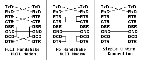
| Sample DTE to DTE "null-modem" wirings |
|
|
The following connector is used for products such as ST-1616, ST-1002, and ST-1008.
                             +--------------------------+
                              | pin | signal | direction |
      Female DB-25 DTE        |--------------------------|
                              |  2  |  TxD   |    out    |
        ___________           |  3  |  RxD   |    in     |
       ( 13......1 )          |  4  |  RTS   |    out    |
        \ 25...14 /           |  5  |  CTS   |    in     |
         `-------'            |  6  |  DSR   |    in     |
                              |  7  |  GND   |    n/a    |
                              |  8  |  DCD   |    in     |
                              | 20  |  DTR   |    out    |
                              +--------------------------+
                           +--------------------------+
                            | pin | signal | direction |
  Male AT-style DB-9 DTE    |--------------------------|
                            |  1  |  DCD   |    in     |
        ___________         |  2  |  RxD   |    in     |
       ( 1.......5 )        |  3  |  TxD   |    out    |
        \ 6.....9 /         |  4  |  DTR   |    out    |
         `-------'          |  5  |  GND   |    n/a    |
                            |  6  |  DSR   |    in     |
                            |  7  |  RTS   |    out    |
                            |  8  |  CTS   |    in     |
                            |  9  |  RI    |    in     |
                            +--------------------------+
Important: This RJ-45 connector information does not apply to the RJ-45 connectors on the old corollary products.
We use our own RJ-45 pin configuration, which is noted where appropriate below. To avoid confusion, an ASCII representation of an RJ-45 receptacle (the female connector like the ones used on our units) is shown below with pin numbering.
This connector is used with products such as Digi EtherLite products, PCI products, and also most of Digi SCSI products.
                           +--------------------------+
    1 2 3 4 5 6 7 8         |     | RS-422 |           |
 .--+-+-+-+-+-+-+-+--.      | pin | signal | direction |
 |  | | | | | | | |  |      |--------------------------|
 |    R-  R+T+  T-   |      |  1  |  RTS * |    out    |
 |                   |      |  2  |  RxD-  |    in     |
 |                   |      |  3  |  DCD * |    in     |
 |                   |      |  4  |  RxD+  |    in     |
 |                   |      |  5  |  TxD+  |    out    |
 '-----.       .-----'      |  6  |  GND * |    n/a    |
       |_     _|            |  7  |  TxD-  |    out    |
         |   |              |  8  |  CTS * |    in     |
         '---'              +--------------------------+
                 .---------------------.
                  | CD RJ-45 | Terminal |
                  |----------+----------|
                  | RxD- (2) | TxD- (?) |
                  | RxD+ (4) | TxD+ (?) |
                  | TxD- (7) | RxD- (?) |
                  | TxD+ (5) | RxD+ (?) |
                  `---------------------'
                           +--------------------------+
    1 2 3 4 5 6 7 8         |     | RS-232 |           |
 .--+-+-+-+-+-+-+-+--.      | pin | signal | direction |
 |  | | | | | | | |  |      |--------------------------|
 |                   |      |  1  |  RTS   |    out    |
 |                   |      |  2  |  DSR   |    in     |
 |                   |      |  3  |  DCD   |    in     |
 |                   |      |  4  |  RxD   |    in     |
 |                   |      |  5  |  TxD   |    out    |
 '-----.       .-----'      |  6  |  GND   |    n/a    |
       |_     _|            |  7  |  DTR   |    out    |
         |   |              |  8  |  CTS   |    in     |
         '---'              +--------------------------+
Here are a few sample wiring configurations to help configure
cables when adapting between Digi RJ45, and DB-25 or DB-9
connectors. These charts may also be used to configure any kind of
adapter between SCSI/EtherLite RJ-45, a DB-25, or a DB-9
connections, but you may need to reorganize the data. It may help
to draw your own "map" before committing the pins in your
connector.
                         +-----------------------------------+
                          | RJ-45 |  RS-232   || DB-25 | DB-9 |
The standard DTE adapter: |  pin  |  signal   ||  pin  | pin  |
------------------------- |-------------------||--------------|
To make an adapter that   |   1   | RTS (out) ||   4   |  7   |
would simply give you     |   2   | DSR (in)  ||   6   |  6   |
a standard DTE DB-25      |   3   | DCD (in)  ||   8   |  1   |
for direct connect with   |   4   | RxD (in)  ||   3   |  2   |
modems, use this          |   5   | TxD (out) ||   2   |  3   |
configuration.            |   6   | GND (n/a) ||   7   |  5   |
                          |   7   | DTR (out) ||  20   |  4   |
                          |   8   | CTS (in)  ||   5   |  8   |
                          +-----------------------------------+
Note: The above adapter is actually converting signals
between different connectors. No signal crosswiring is taking
place.
                          +---------------------------------------------+
                          | RJ-45 |  RJ-45    ||   DST*   |DB-25 | DB-9 |
The custom DCE adapter:   |  pin  |  signal   ||  signal  | pin  | pin  |
------------------------- |-------------------||------------------------|
To make an adapter that   |   1   | RTS (out) || CTS (in) |  5   |  8   |
would allow you to        |   2   | DSR (in)  ||  ------  | n/c  | n/c  |
directly connect to       |   3   | DCD (in)  || DTR (out)| 20   |  4   |
terminals and most        |   4   | RxD (in)  || TxD (out)|  2   |  3   |
printers, use this        |   5   | TxD (out) || RxD (in) |  3   |  2   |
configuration.            |   6   | GND (n/a) || GND (n/a)|  7   |  5   |
                          |   7   | DTR (out) || DCD (in) |  8   |  1   |
                          |   8   | CTS (in)  || RTS (out)|  4   |  7   |
                          +---------------------------------------------+
If you use this type of cable with Central Data's connectors, among other things, RxD (receive) and TxD (transmit) will be twisted together, and be subject to crosstalk interference. The net result is that reliability decreases as cable length and/or baud rates increase.
There is a way to use Cat 5 cable with modular RS-232, but you have to do some special wiring. First, you have to know which wires are twist pairs. One wire in each twisted pair (of four total) must be grounded. This means you only have 4 actual RS-232 signals you can use, but the configuration will be very reliable. Most people opt to run RxD, TxD, DTR, and DCD. This does everything except hardware flow control, which is fine for most terminals and serial printers.
(DTE)           (DTE)
-----           -----
 SG  ----------- SG
 TxD ----------- RxD
 RxD ----------- TxD
 RTS ----------- CTS
 CTS ----------- RTS
 DSR --+
 DCD --+-------- DTR
 GND ----------- GND
 DTR --------+-- DSR
             +-- DCD

Example pin connections:
------------------------

DB-25 -> DB-25                CD RJ-45 -> DB-25
--------------                -----------------
    2 -> 3       TxD - RxD          5 -> 3
    3 -> 2       RxD - TxD          4 -> 2
    4 -> 5       RTS - CTS          1 -> 5
    5 -> 4       CTS - RTS          8 -> 4
    7 -> 7       GND - GND          6 -> 7
  6+8 -> 20     DSR+DCD - DTR       3 -> 20  (DCD - DTR)
   20 -> 6+8    DTR - DSR+DCD       7 -> 8   (DTR - DCD)
                                    2 -> n/c or pin 6 (see note below)
(DTE)           (DTE)
-----           -----
 SG) ----------- SG
 TxD ----------- RxD
 RxD ----------- TxD
 DCD --+     +-- DCD |
 DSR --+     +-- DSR |- modem control loopback
 DTR --+     +-- DTR |
 GND ----------- GND
 RTS --+     +-- CTS |
 CTS --+     +-- RTS |- hardware flow control loopback

Example pin connections:
------------------------

DB-25 -> DB-25           CD RJ-45 -> DB-25
--------------           -----------------
    2 -> 3     TxD - RxD       5 -> 3
    3 -> 2     RxD - TxD       4 -> 2
    6+8+20    DSR+DCD+DTR      2, 3, and 7 not connected. (see note below)
    7 -> 7     GND - GND       6 -> 7
    4+5         RTS+CTS        1 and 8 not connected. (see note below)
Some terminals are designed to use DTR and CTS for hardware flow control instead of the more common RTS/CTS pairing. Some serial printers are also designed this way. In these cases, the following diagram can be used:
(DTE)      (Terminal/Printer)
-----      ------------------
 SG  ------------- SG
 TxD ------------- RxD
 RxD ------------- TxD
 RTS ------------- CTS
 CTS ------------- DTR
 GND ------------- GND
 DSR --+
 DCD --+
 DTR --+

Example pin connections:
------------------------

DB-25 -> DB-25              CD RJ-45 -> DB-25
--------------              -----------------
     2 -> 3      TxD - RxD        5 -> 3
     3 -> 2      RxD - TxD        4 -> 2
     4 -> 5      RTS - CTS        1 -> 5
     5 -> 20     CTS - DTR        8 -> 20
     7 -> 7      GND - GND        6 -> 7
6+8+20 -> n/c   DSR+DCD+DTR       2 -> not connected. +
                                  3 -> not connected. +-(see note below)
                                  7 -> not connected. +