Getting Started
| Rabbit 2000 Dev Kit Getting Started |
|
2. Detailed Installation Instructions
Chapter 2 contains detailed instructions for installing the software on your PC and for connecting the BL1810 to your PC in order to run sample programs.
2.1 Software Installation
You will need approximately 200 megabytes of free space on your hard disk for a complete installation. The software can be installed on your C drive or any other convenient drive.
Insert the Dynamic C CD-ROM in the drive on your PC. If autorun is enabled, the CD installation will begin automatically.
If autorun is disabled or the installation otherwise does not start, use the Windows Start | Run menu or Windows Disk Explorer to launch SETUP.EXE from the root folder of the CD-ROM.
The installation program will guide you through the installation process.
2.2 Prototyping Board
The Prototyping Board included in the Development Kit makes it easy to connect a BL1810 to a power supply and a PC workstation for development. It also provides some basic I/O peripherals (switches and LEDs), as well as a prototyping area for more advanced hardware development.
For the most basic level of evaluation and development, the Prototyping Board can be used without modification.
As you progress to more sophisticated experimentation and hardware development, modifications and additions can be made to the board without modifying or damaging the BL1810 itself.
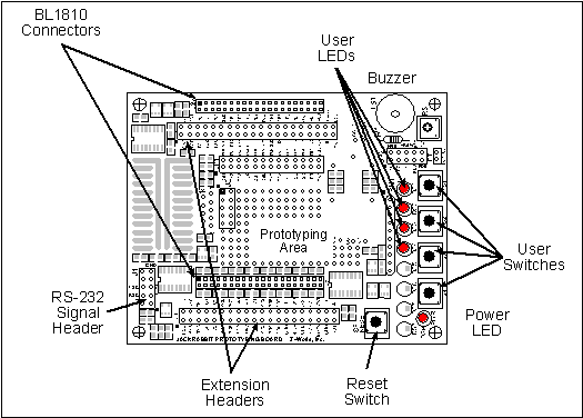
The Prototyping Board is shown below in Figure 1, with its main features identified.
2.2.1 Prototyping Board Features
- Power LED--The power LED lights whenever power is connected to the Prototyping Board.
- Reset Switch--A momentary-contact, normally open switch is connected directly to the BL1810's /RESET_IN pin. Pressing the switch forces a hardware reset of the system.
- I/O Switches and LEDs--Four momentary-contact, normally open switches are connected to the PB2-PB5 pins of the Rabbit 2000 microprocessor on the BL1810, and may be read as inputs by sample applications.
Four LEDs are connected to the PA1-PA4 pins of the of the Rabbit 2000 microprocessor on the BL1810, and may be driven as output indicators by sample applications.
- Prototyping Area--A generous prototyping area has been provided for the installation of through-hole components. Several areas for surface-mount devices are also available. (Note that there are SMT device pads on both top and bottom of the Prototyping Board.)
- Extension Headers--The complete pin sets of the BL1810 are duplicated at these two sets of headers. Developers can solder wires directly into the appropriate holes, or, for more flexible development, 40-pin header strips can be soldered into place. See Figure A-1 for the header pinouts.
- RS-232--Two 3-wire or one 5-wire RS-232 serial port are available on the Prototyping Board. Refer to the Prototyping Board schematic (090-0088) for additional details.
A 10-pin 0.1-inch spacing header strip is installed at J1 to permit connection of a ribbon cable leading to a standard DE-9 serial connector.
2.3 Development Hardware Connections
There are three steps to connecting the Prototyping Board for use with Dynamic C and the sample programs:
- Attach the BL1810 to the Prototyping Board.
- Connect the programming cable between the BL1810 and the workstation PC.
- Connect the power supply to the BL1810.
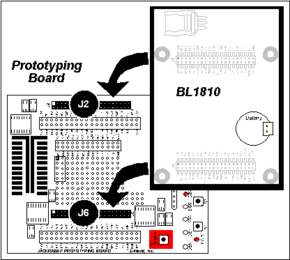
2.3.1 Attach BL1810 to Prototyping Board
To attach the BL1810 to the Prototyping Board, turn the BL1810 over so that the battery is facing up. Plug the pins from headers J4 and J5 on the bottom side of the BL1810 into the header sockets at J2 and J6 on the Prototyping Board as indicated in Figure 2.
Press the BL1810's pins firmly into the Prototyping Board headers.
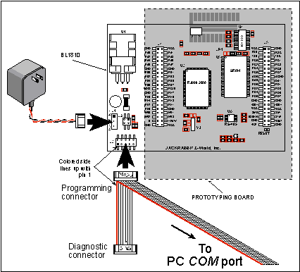
2.3.2 Connect Programming Cable
The programming cable connects the BL1810 to the PC running Dynamic C to download programs and to monitor the BL1810 during debugging.
Connect the 10-pin connector of the programming cable labeled PROG to header J3 on the BL1810 as shown in Figure 3. Be sure to orient the marked (usually red) edge of the cable towards pin 1 of the connector. (Do not use the DIAG connector, which is used for a normal serial connection.)
Connect the other end of the programming cable to a COM port on your PC.
2.3.3 Connect Power
When all other connections have been made, you can connect power to the BL1810.
Hook up the connector from the wall transformer to header J1 on the BL1810 as shown in Figure 3. The orientation of this connector is not important since the VIN (positive) voltage is the middle pin, and GND is available on both ends of the three-pin header J1.
Plug in the wall transformer. The BL1810 and the Prototyping Board are ready to be used.
NOTE A RESET button is provided on the Prototyping Board (see Figure 3) to allow hardware reset without disconnecting power. To power down the BL1810, unplug the power connector from J1. You should disconnect power before making any circuit adjustments in the prototyping area, changing any connections to the board, or removing the BL1810 from the Prototyping Board.
2.3.3.1 Overseas Development Kits
Development kits sold outside North America include a header connector that may be connected to 3-pin header J1 on the BL1810. The connector may be attached either way as long as it is not offset to one side. The red and black wires from the connector can then be connected to the positive and negative connections on your power supply. The power supply should deliver 7.5 V-25 V DC at 5 W.
2.4 Start Dynamic C
Once the BL1810 is connected as described in Section 2.3, start Dynamic C by double-clicking on the Dynamic C icon or by double-clicking on
dcrabXXXX.exein the Dynamic C root directory, whereXXXXare version-specific characters.If you are using a USB port to connect your computer to the BL1810, choose Options > Project Options and select "Use USB to Serial Converter" under the Communications tab.
2.5 Run a Sample Program
Find the file PONG.C, which is in the Dynamic C SAMPLES folder. To run the program, open it with the File menu (if it is not still open), compile it using the Compile menu, and then run it by selecting Run in the Run menu. The STDIO window will open and will display a small square bouncing around in a box.
This program shows that the CPU is working.
2.5.1 Troubleshooting
If Dynamic C appears to compile the BIOS successfully, but you then receive a communication error message when you compile and load the sample program, it is possible that your PC cannot handle the higher program-loading baud rate. Try changing the maximum download rate to a slower baud rate as follows.
- Locate the Serial Options dialog in the Dynamic C Options > Project Options > Communications menu. Select a slower Max download baud rate.
If a program compiles and loads, but then loses target communication before you can begin debugging, it is possible that your PC cannot handle the default debugging baud rate. Try lowering the debugging baud rate as follows.
- Locate the Serial Options dialog in the Dynamic C Options > Project Options > Communications menu. Choose a lower debug baud rate.
If there are any other problems:
- Check to make sure you are using the PROG connector, not the DIAG connector, on the programming cable.
- Check both ends of the programming cable to ensure that they are firmly plugged into the PC and the programming port on the BL1810.
- Ensure that the BL1810 is firmly and correctly installed in its connectors on the Prototyping Board.
- Select a different COM port within Dynamic C. From the Options menu, select Project Options, then select Communications. Select another COM port from the list, then click OK. Press <Ctrl-Y> to force Dynamic C to recompile the BIOS. If Dynamic C still reports it is unable to locate the target system, repeat the above steps until you locate the active COM port.
2.6 Where Do I Go From Here?
If everything appears to be working, we recommend the following sequence of action:
- Run all of the sample programs described in Chapter 3 to get a basic familiarity with Dynamic C and the BL1810's capabilities.
- For further development, refer to the Jackrabbit (BL1800) User's Manual for details of the board's hardware components.
A documentation icon should have been installed on your workstation's desktop; click on it to reach the documentation menu. You can create a new desktop icon that points to default.htm in the docs folder in the Dynamic C installation folder.
- For advanced development topics, refer to the Dynamic C User's Manual, also in the online documentation set.
2.6.1 Technical Support
NOTE If you purchased your Rabbit 2000 Development Kit through a distributor or through a Rabbit Semiconductor partner, contact the distributor or partner first for technical support. If there are any problems at this point:
- Use the Dynamic C Help menu to get further assistance with Dynamic C.
- Check the Z-World/Rabbit Semiconductor Technical Bulletin Board at www.zworld.com/support/bb/.
- Use the Technical Support e-mail form at www.zworld.com/support/questionSubmit.shtml.
| Z-World, Inc. www.zworld.com Phone: 1.530.757.3737 FAX: 1.530.757.3792 |