Getting Started
| Rabbit 2000 Dev Kit Getting Started |
|
4. Software Reference
To develop and debug programs for the BL1810 (and for all other Z-World and Rabbit Semiconductor hardware), you must install and use Dynamic C. It runs on an IBM-compatible PC and is designed for use with Z-World single-board computers and other devices based on the Rabbit microprocessor. This chapter provides a tour of the major features of Dynamic C with respect to the BL1810.
4.1 An Overview of Dynamic C
Dynamic C has been in use worldwide since 1989. It is specially designed for programming embedded systems, and features quick compile and interactive debugging. A complete reference guide to Dynamic C is contained in the Dynamic C User's Manual.
You have a choice of doing your software development in the flash memory or in the data SRAM included on the BL1810. The flash memory and SRAM options are selected with the Options > Project Options > Compiler menu.
The advantage of working in RAM is to save wear on the flash memory, which is limited to about 100,000 write cycles. The disadvantage is that the code and data might not both fit in RAM.
Developing software with Dynamic C is simple. Users can write, compile, and test C and assembly code without leaving the Dynamic C development environment. Debugging occurs while the application runs on the target. Alternatively, users can compile a program to an image file for later loading. Dynamic C runs on PCs under Windows 95, 98, 2000, NT, Me, and XP. Programs can be downloaded at baud rates of up to 460,800 bps.
Dynamic C has a number of standard features:
- Full-feature source and/or assembly-level debugger, no in-circuit emulator required.
- Royalty-free TCP/IP stack with source code and most common protocols.
- Hundreds of functions in source-code libraries and sample programs:
u Exceptionally fast support for floating-point arithmetic and transcendental functions.
u RS-232 and RS-485 serial communication.
u Analog and digital I/O drivers.
u LCD display and keypad drivers.
- Powerful language extensions for cooperative or preemptive multitasking
- Loader utility program to load binary images into Z-World targets in the absence of Dynamic C.
- Provision for customers to create their own source code libraries and augment on-line help by creating "function description" block comments using a special format for library functions.
- Standard debugging features:
u Breakpoints--Set breakpoints that can disable interrupts.
u Single-stepping--Step into or over functions at a source or machine code level, µC/OS-II aware.
u Code disassembly--The disassembly window displays addresses, opcodes, mnemonics, and machine cycle times. Switch between debugging at machine-code level and source-code level by simply opening or closing the disassembly window.
u Watch expressions--Watch expressions are compiled when defined, so complex expressions including function calls may be placed into watch expressions. Watch expressions can be updated with or without stopping program execution.
u Register window--All processor registers and flags are displayed. The contents of general registers may be modified in the window by the user.
u Stack window--shows the contents of the top of the stack.
u Hex memory dump--displays the contents of memory at any address.
u STDIO window--
printfoutputs to this window and keyboard input on the host PC can be detected for debugging purposes.printfoutput may also be sent to a serial port or file.4.1.1 Upgrading Dynamic C
4.1.1.1 Patches and Bug Fixes
Dynamic C patches that focus on bug fixes are available from time to time. Check the Web site
for the latest patches, workarounds, and bug fixes.
The default installation of a patch or bug fix is to install the file in a directory (folder) different from that of the original Dynamic C installation. Z-World recommends using a different directory so that you can verify the operation of the patch without overwriting the existing Dynamic C installation. If you have made any changes to the BIOS or to libraries, or if you have programs in the old directory (folder), make these same changes to the BIOS or libraries in the new directory containing the patch. Do not simply copy over an entire file since you may overwrite a bug fix; of course, you may copy over any programs you have written. Once you are sure the new patch works entirely to your satisfaction, you may retire the existing installation, but keep it available to handle legacy applications.
4.1.2 Add-On Modules
Dynamic C installations are designed for use with the board they are included with, and are included at no charge as part of our low-cost kits. Z-World offers add-on Dynamic C modules for purchase, including the popular µC/OS-II real-time operating system, as well as PPP, Advanced Encryption Standard (AES), and other select libraries.
In addition to the Web-based technical support included at no extra charge, a one-year telephone-based technical support module is also available for purchase.
4.2 BL1810 Function Calls
4.2.1 I/O Drivers
The BL1810 contains four high-power digital output channels, two D/A converter output channels, and one A/D converter input channel. These I/O channels can be accessed using the functions found in the
JRIO.LIBlibrary.4.2.1.1 Initialization
The function
jrioInit()must be called before any other function from theJRIO.LIBlibrary. This function initializes the digital outputs and sets up the driver for the analog input/outputs. The digital outputs correspond to the Rabbit processor's port E bits 0-3, and the analog I/O uses timer B; bits 1, 2, and 4 of port D; and bits 6 and 7 of port E.The function void
jrioInit()initializes the I/O drivers for BL1810. In particular, it sets up parallel port D bits 1, 2, and 4 for analog output, port E bits 0-3 for digital output, and starts up the pulse-width modulation routines for the A/D and D/A channels. Note that these routines can consume up to 20% of the CPU's processing power; the routines use timer B and the B1 and B2 match registers.4.2.1.2 Digital Output
The BL1810 contains four high-power digital output drivers, HV0-HV3, on header J4. These can be turned on and off with the following functions from the library
JRIO.LIB.HV0, HV1, and HV2 are open-collector sinking outputs, and are able to sink up to 1 A (200 mA for the BL1810 and BL1820) from a 30 V source connected to the K line on header J4. HV3 is a sourcing output that is able to source up to 500 mA (100 mA for the BL1810 and BL1820) from a 30 V source connected to the K line.
CAUTION: 
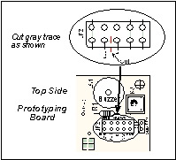
Remember to cut the trace between K and Vcc inside the outline for header JP2 on the top side of the Prototyping Board if you are supplying K from a separate power supply. An exacto knife, a precision grinder tool, or a screwdriver may be used to cut through the traces as shown in Figure 7.
NOTE Failure to do this could lead to the destruction of the Rabbit 2000 microprocessor and other components once the BL1810 is connected to the Prototyping Board.
void digOut(int channel, int value);
- sets the state of a digital output bit.
jrioInitmust be called first.
channelis the output channel number (0-3 on the BL1810).
valueis the output value (0 or 1).
- sets the state of a digital output bit to on (1).
jrioInitmust be called first.
channelis the output channel number (0-3 on the BL1810).
- sets the state of a digital output bit to off (0).
jrioInitmust be called first.
channelis the output channel number (0-3 on the BL1810).
NOTE See the sample program JRIOTEST.Cfor an example of using the digital output functions.4.2.1.3 Analog Output
The two analog output channels on the BL1810 (DA0 and DA1 on header J5) are controlled by a pulse-width modulation (PWM) driver. This requires the use of some fraction of the CPU cycles when the driver is running (up to 20% when both D/A channels are used). A voltage is selected by giving a value from 0 to 1024 to the driver, corresponding roughly to 0.1 V to 3.5 V on DA0. Because of the PWM interrupt frequency, the PWM driver can provide a continuous range of voltage output in the range from 0.1 V to 3.0 V for DA0, and 0.6 V to 3.6 V for DA1. These ranges can be specified with the constants
PWM_MIN,PWM_MAX0, andPWM_MAX1. In other words, setting channel DA0 to the valuePWM_MINwill output 0.1 V, and setting it toPWM_MAX0will output 3.0 V. Similarly, setting DA1 toPWM_MINwill output 0.6 V, and setting it toPWM_MAX1will output 3.6 V. Values belowPWM_MINwill be rounded down to 0, and values abovePWM_MAX0(PWM_MAX1for DA1) will be rounded up to 1024.The output channels can also be set in an "always on" or "always off" mode, which does not require CPU cycles. The "always on" mode is set by requesting an output value of 1024, and will provide about 3.4 V on channel DA0, and 3.6 V on DA1. The "always off" mode is selected by asking for a value of 0, and provides an output of around 0.1 V on DA0 and 0.0 V on DA1.
See Table 2 for a summary of the possible analog output voltages corresponding to values given in the
anaOutfunction.
Table 2. Typical Analog Output Voltages Corresponding
to Values in anaOut Function
The output value is set using the following function.
void anaOut(int channel, int value);
- sets the state of an analog output channel.
jrioInitmust be called first.
channelis the output channel number (0 or 1 on the BL1810).
valueis an integer from 0-1024 that corresponds to an output voltage as shown in Table 2.
NOTE See the sample program JRIOTEST.Cfor examples of using theanaOutfunction.Effect of Interrupts on Analog I/O
The stability of the voltage output (and hence the voltage input determination as well) depends on the ability of the driver to respond quickly to interrupt requests. Dynamic C debugging, use of the
printffunction, or any serial communications can disrupt the pulse-width modulation utilized by the driver and cause fluctuations in the voltage outputs. Avoid using serial communications orprintfstatements during portions of your program where the voltage must remain steady. Also be aware that debugging and running Dynamic C in polling mode will cause fluctuations. Finally, be certain to disable the PWM drivers by setting the output values to 0 or 1024 when you are done using them to free up the CPU.Calibration of Values to Voltages
The analog output channels on the BL1810 can be more accurately calibrated for each individual BL1810 in the following manner (calibration of DA0 is assumed in this example, calibration of DA1 would proceed similarly):
- Set desired channel output to
PWM_MIN.
- Measure voltage Vmin on DA0.
- Set desired channel output to
PWM_MAX0.
- Measure voltage Vmax on DA0.
- A linear relation between input value and voltage can now be calculated:
4.2.1.4 Analog Input
The analog input channel on the BL1810 (AD0 on header J5) works by varying analog output channel DA0 until its voltage matches the input voltage on AD0. DA0 obviously cannot be used while an input voltage is being measured, although channel DA0 is still available. The value returned corresponds to the value that DA0 required to match the input voltage (you would call
anaOut(0,value)for DA0 to provide that same voltage). If the value returned is negative, then the function considers the value suspect for some reason (most likely a failure of the DA0 voltage to settle quickly). The value can be taken as is, or another measurement can be done.
void anaIn(int channel, int *value);
- Analog input for the BL1810 analog input channel (AD0).
jrioInitmust be called first.
channelis the input channel number (0 only on the BL1810).An integer between 0 and 1024 will be returned in
value, corresponding to a voltage obtained if output channel DA0 was set to that value. If a value is found, but the voltage has not appeared to fully settle, the value will be negative (but equal in magnitude to the found voltage) to allow remeasurement if desired.
NOTE See sample program JRIOTEST.Cfor an example of the use ofanaIn.Two versions of the analog input function are available: the standard function, listed above, that does not return until the measurement has been made, and a cofunction version that can be called from within a costatement. This cofunction version allows other tasks to be performed while the voltage match is being made. The voltage measurement will take ten calls of the cofunction version to make a measurement.
void cof_anaIn(int channel, int *value);
- The parameters are identical to those described above for
anaIn.
NOTE See sample program JRIO_COF.Cfor an example of the use ofcof_anaIn.4.2.2 Serial Communication Drivers
Library files included with Dynamic C provide a full range of serial communications support. The
RS232.LIBlibrary provides a set of circular-buffer-based serial functions. ThePACKET.LIBlibrary provides packet-based serial functions where packets can be delimited by the 9th bit, by transmission gaps, or with user-defined special characters. Both libraries provide blocking functions, which do not return until they are finished transmitting or receiving, and nonblocking functions, which must be called repeatedly until they are finished. For more information, see the Dynamic C Function Reference Manual and Technical Note 213, Rabbit 2000 Serial Port Software.4.2.2.1 RS-485 Serial Communication Drivers
The
JR485.LIBlibrary in the Dynamic CLIB/JRABLIBdirectory contains three RS-485 drivers for use with the BL1810. These drivers are used with the drivers for Serial Port D in theRS232.LIBlibrary becauseserDopenuses PC0 (TXD) and PC1 (RXD), which are connected to pin 4 and pin 1 of the SP483EN RS-485 chip at U6. This chip is half duplex, requiring pin 3 (Data Enable) to be high for pins 6 and 7 to act as outputs, and low for those pins to act as inputs.Parallel Ports D and E on the Rabbit 2000 are double-buffered to provide precisely timed updating of the output pins. Each port is divided into an upper and a lower nibble. All bits of each nibble must be updated simultaneously. Each nibble may be updated constantly at a rate of
perclk/2 or on a match of a selected timer (Timer A1, B1, or B2).The bits used to select the update rate for each nibble are left random at power-up. If a mode other than
perclk/2 is selected, the bits of a particular port will not update on a simple writing to the port's data register. In particular, PD5, the RS-485 transmitter control, will not set the RS-485 transmitter enable unless the upper nibble of Port D is configured properly.The
JR485Initfunction in Dynamic C release 6.16 has provision to disable the special clocking features associated with the high nibble of Port D. This effectively disables digital-to-analog (D/A) converter output channel DA1, the low-resolution D/A converter channel, which also uses PD4. Channel DA0 has its PWM output clocked separately with the low nibble, and so is not affected. Because the analog-to-digital converter uses D/A channel DA0, analog-to-digital conversion is not affected.There are three RS-485 serial drivers.
- Sets up parallel port D pins for RS-485 use.
- Sets pin 3 (DE) of the SP483EN chip high to disable Rx and enable Tx.
- Resets pin 3 (DE) of the SP483EN chip low to disable Tx and enable Rx.
| Z-World, Inc. www.zworld.com Phone: 1.530.757.3737 FAX: 1.530.757.3792 |