
Administering WAN lines and calls
The MAX allows you to manage WAN lines, ports, and modems. This section describes how to:
Quiescing a modem or modem slot does not result in active calls being torn down. Instead, when active call drops, that modem or modem slot is added to a disabled list and is unavailable for use. If all modems are disabled, incoming callers receive a busy signal until the modems have been restored for service. A quiesced modem is available for use approximately 20 seconds after it has been re-enabled.
To quiesce a modem or modem slot, access the V.34 (V.42) Modem > Modem Diag menu.
To quiesce a modem, use the Modem #N command, where N is the modem number from 1 to 12. You can set one of the following values:
To quiesce a modem slot, use the ModemSlot command. You can set one of the following values:
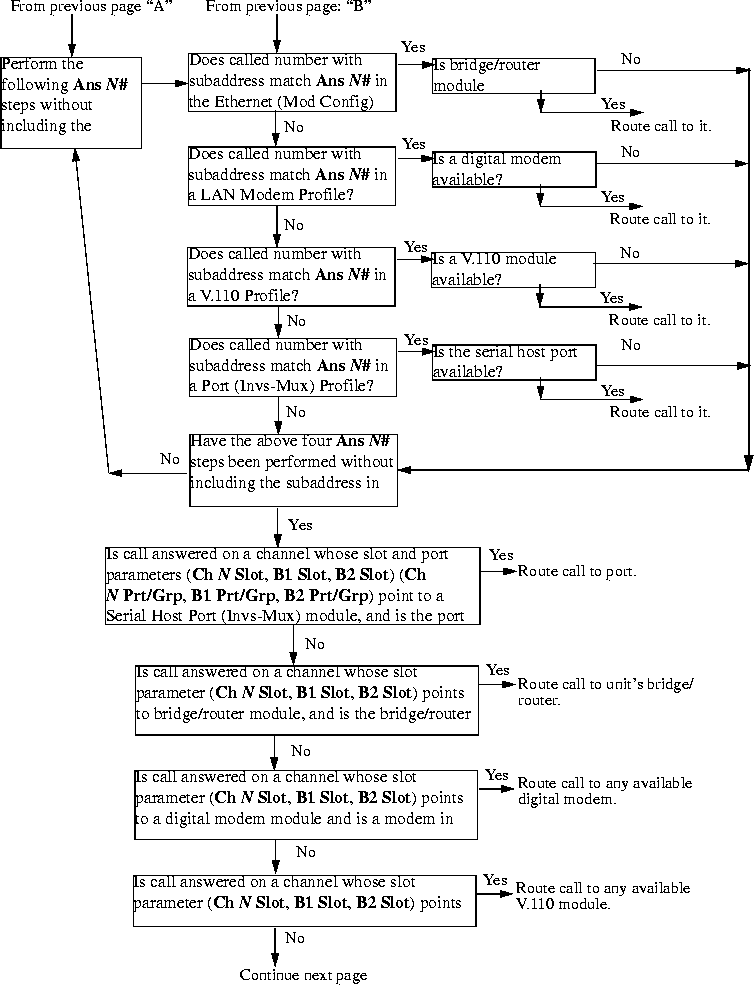
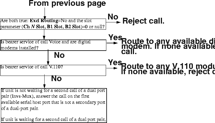
Incoming call routing state diagram
The following pages show detailed state information about inbound call routing in the MAX. For more information about any of the parameters, see the MAX Reference Guide.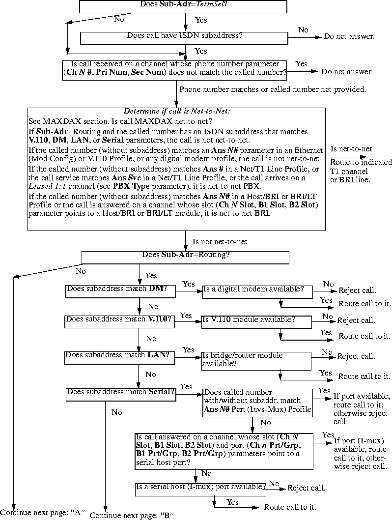
Managing IP routes and sessions
This section describes how to monitor TCP/IP/UDP and related information in the terminal-server command-line interface. To invoke the terminal-server interface, select System > Sys Diag > Term Serv and press Enter. The terminal-server command-line prompt appears: ascend%. Working with the IP routing table
The terminal-server IProute commands display the routing table and enable you to add or delete routes. The changes you make to the routing table by using the IProute command last only until the MAX unit is reset. To display the IProute commands, enter the IP route command with a question mark:
ascend% iproute ?
iproute ?              Display help information

iproute add          iproute add <destination/size> <gateway> [ pref ] [ m

iproute delete    iproute delete <destination/size> <gateway> [ proto ]

iproute show        displays IP routes (same as "show ip routes" command)
ascend% iproute show
Destination        Gateway        IF       Flg Pref  Met   Use   Age

0.0.0.0/0          10.0.0.100     wan0     SG   1     1     0     20887

10.207.76.0/24     10.207.76.1    wanidle0 SG   100   7     0     20887

10.207.77.0/24     10.207.76.1    wanidle0 SG   100   8     0     20887

127.0.0.1/32       -              lo0      CP   0     0     0     20887

10.0.0.0/24        10.0.0.100     wan0     SG   100   1     21387 20887

10.1.2.0/24        -              ie0      C    0     0     19775 20887

10.1.2.1/32        -              lo0      CP   0     0     389   20887

255.255.255.255/32 -              ie0      CP   0     0     0     20887
0.0.0.0/0 10.0.0.100 wan0 SG 1 1 0 20887
10.207.76.0/24 10.207.76.1 wanidle0 SG 100 7 0 20887
10.207.77.0/24 10.207.76.1 wanidle0 SG 100 8 0 20887
127.0.0.1/32 - lo0 CP 0 0 0 20887
The next route is specified in a Connection profile that is currently active:
10.0.0.0/24 10.0.0.100 wan0 SG 100 1 21387 20887
10.1.2.0/24 - ie0 C 0 0 19775 20887
10.1.2.1/32        -              lo0      CP   0     0     389   20887

255.255.255.255/32 -              ie0      CP   0     0     0     20887
iproute add destination gateway [metric]
destination is the destination network address, gateway is the IP address of the router that can forward packets to that network, and metric is the virtual hop count to the destination network (default 8). For example, to add a route to the 10.1.2.0 network and all of its subnets through the IP router located at 10.0.0.3/24 with a metric of 1 (the router is one hop away), enter the following command:
ascend% iproute add 10.1.2.0 10.0.0.3/24 1If you try to add a route to a destination that already exists in the routing table, the MAX replaces the existing route, but only if it has a higher metric than the new route. If you get the message
Warning: a better route appears to exist, the MAX has rejected your attempt to add a route because the routing table already contained a route, to the same destination, with a lower metric. Note that RIP updates can change the metric for the route.
iproute delete destination gateway
ascend% iproute delete 10.1.2.0 10.0.0.3/24
Displaying route statistics
The Traceroute command is useful for locating slow routers or diagnosing IP routing problems. It traces the route an IP packet follows by launching UDP probe packets with a low Time-To-Live (TTL) value and then listening for an ICMP time exceeded reply from a router. The Traceroute command uses the following syntax:
All flags are optional. The only required parameter is the destination hostname or IP address. The elements of the syntax are as follows:traceroute[-n] [-v] [-mmax_ttl][-pport] [-qnqueries]
[-wwaittime] host [datasize]
For example, to trace the route to the host
techpubs:
ascend% traceroute techpubs
traceroute to techpubs (10.65.212.19), 30 hops MAX, 0 byte packetsProbes start with a TTL of one and increase by one until one of the following conditions occurs:
1 techpubs.eng.ascend.com (10.65.212.19) 0 ms 0 ms 0 ms
ascend% traceroute -m 60 techpubs
traceroute to techpubs (10.65.212.19), 60 hops MAX, 0 byte packetsThree probes are sent at each TTL setting. The second line of command output shows the address of the router and round trip time of each probe. If the probe answers come from different gateways, the address of each responding system is shown. If there is no response within a three second timeout interval, the command output is an asterisk. The following annotations can appear after the time field in a response:
1 techpubs.eng.abc.com (10.65.212.19) 0 ms 0 ms 0 ms
!H-Host reached.
!N-Network unreachable.
!P-Protocol unreachable.
!S-Source route failed. Might indicate a problem with the associated device.
!F-Fragmentation needed. Might indicate a problem with the associated device.
!h-Communication with the host is prohibited by filtering.
!n-Communication with the network is prohibited by filtering.
!c-Communication is otherwise prohibited by filtering.
!?-ICMP subcode detected. This event should not occur.
!??-Reply received with inappropriate type. This event should not occur.
All flags are optional. The only required parameter is the destination hostname or IP address. The elements of the syntax are as follows:ping[-q] [-v] [-ccount] [-isec |-Imsec] [-spacketsize]
[-xsrc_address] host
For example, to Ping the host
techpubs:
ascend% ping techpubs
PING techpubs (10.65.212.19): 56 data bytesYou can terminate the Ping exchange at any time by pressing Ctrl-C. When you press Ctrl-C, the command reports the number of packets sent and received, the percentage of packet loss, any duplicate or damaged echo-response packets, and round-trip statistics. In some cases, round-trip times cannot be calculated.
64 bytes from 10.65.212.19: icmp_seq=0 ttl=255 time=0 ms
64 bytes from 10.65.212.19: icmp_seq=3 ttl=255 time=0 ms
^C
--- techpubs ping statistics ---
2 packets transmitted, 2 packets received, 0% packet loss
round-trip min/avg/MAX = 0/0/0 ms
During the Ping exchange, the MAX displays information about the packet exchange, including the Time-To-Live (TTL) of each ICMP echo-response packet.
The Ping command sends an ICMP Mandatory echo-request datagram, which asks the remote station "Are you there?" If the echo-request reaches the remote station, the station sends back an ICMP echo-response datagram, which tells the sender "Yes, I am alive." This exchange verifies that the transmission path is open between the MAX and a remote station.
Configuring the DNS Fallback Table
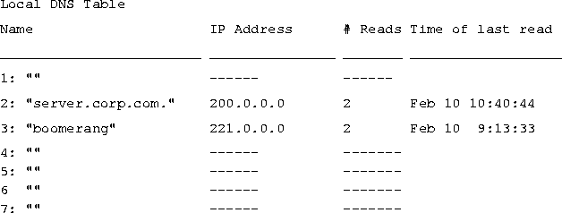
The local DNS table provides a list of IP addresses for a specific host name when the remote DNS server fails to resolve the host name. If the local DNS table contains the host name for the attempted connection, it provides the list of IP addresses.
Figure 5-1. Example of a local DNS table
Displaying IP routing and related information
The following Show commands for monitoring IP routing and related protocols are described in this section:
show arp		Display the Arp Cache

show icmp		Display ICMP information

show if	Display Interface info. Type 'show if ?' for help.

show ip	Display IP information. Type 'show ip ?' for help.

show udp	Display UDP information. Type 'show udp ?' for help.

show tcp	Display TCP information. Type 'show tcp ?' for help.

show pools	Display the assign address pools.
ascend% show arp
entry typ ip address ether addr if rtr pkt insertThe ARP table displays the following information:
0 DYN 10.65.212.199 00C07B605C07 0 0 0 857783
1 DYN 10.65.212.91 0080C7C4CB80 0 0 0 857866
2 DYN 10.65.212.22 080020792B4C 0 0 0 857937
3 DYN 10.65.212.3 0000813DF048 0 0 0 857566
4 DYN 10.65.212.250 0020AFF80F1D 0 0 0 857883
5 DYN 10.65.212.16 0020AFEC0AFB 0 0 0 857861
6 DYN 10.65.212.227 00C07B5F14B6 0 0 0 857479
7 DYN 10.65.212.36 00C07B5E9AA5 0 0 0 857602
8 DYN 10.65.212.71 0080C730041F 0 0 0 857721
9 DYN 10.65.212.5 0003C6010512 0 0 0 857602
10 DYN 10.65.212.241 0080C72ED212 0 0 0 857781
11 DYN 10.65.212.120 0080C7152582 0 0 0 857604
12 DYN 10.65.212.156 0080A30ECE6D 0 0 0 857901
13 DYN 10.65.212.100 00C07B60E28D 0 0 0 857934
14 DYN 10.65.212.1 00000C065D27 0 0 0 857854
15 DYN 10.65.212.102 08000716C449 0 0 0 857724
16 DYN 10.65.212.33 00A024AA0283 0 0 0 857699
17 DYN 10.65.212.96 0080C7301792 0 0 0 857757
18 DYN 10.65.212.121 0080C79BF681 0 0 0 857848
19 DYN 10.65.212.89 00A024A9FB99 0 0 0 857790
20 DYN 10.65.212.26 00A024A8122C 0 0 0 857861
21 DYN 10.65.212.6 0800207956A2 0 0 0 857918
22 DYN 10.65.212.191 0080C75BE778 0 0 0 857918
23 DYN 10.65.212.116 0080C72F66CC 0 0 0 857416
24 DYN 10.65.212.87 0000813606A0 0 0 0 857666
25 DYN 10.65.212.235 00C07B76D119 0 0 0 857708
26 DYN 10.65.212.19 08002075806B 0 0 0 857929
entry-A unique identifier for each ARP table entry.
typ-How the address was learned, dynamically (DYN) or statically (STAT).
ip address-The address contained in ARP requests.
ether addr-The MAC address of the host with that IP address.
if-The interface on which the MAX received the ARP request.
rtr-The next-hop router on the specified interface.
Show icmp command. For example:
ascend% show icmp
3857661 packet received.The Input and Output histograms show the number of ICMP packets received and transmitted, respectively.
20 packets received with errors.
Input histogram: 15070
2758129 packets transmitted.
0 packets transmitted due to lack of resources.
Output histogram: 15218
ascend% show if ?
show if ? Display help informationTo display the status and packet count of each active WAN link and of local and loopback interfaces, enter the Show IF Stats command. For example:
show if stats Display Interface Statistics
show if totals Display Interface Total counts
ascend% show if stats
Interface Name Status Type Speed MTU InPackets OutpacketThe output contains the following fields:
ie0 ethernet Up 6 10000000 1500 107385 85384
wan0 Down 1 0 1500 0 0
wan1 Down 1 0 1500 0 0
wan2 Down 1 0 1500 0 0
wanidle0 Up 6 10000000 1500 0 0
lo0 loopback Up 24 10000000 1500 0 0
ascend% show if totals
Name --Octets----Ucast-- -NonUcast- Discard -Error- Unknown -Same IF-The output contains the following fields:
ie0 i: 7813606 85121 22383 0 0 0 0
o: 101529978 85306 149 0 0 0 0
wan0 i: 0 0 0 0 0 0 0
o: 0 0 0 0 0 0 0
wan1 i: 0 0 0 0 0 0 0
o: 0 0 0 0 0 0 0
wan2 i: 0 0 0 0 0 0 0
o: 0 0 0 0 0 0 0
wanidle0 i: 0 0 0 0 0 0 0
o: 0 0 0 0 0 0 0
lo0 i: 0 0 0 0 0 0 0
o: 0 0 0 0 0 0 0
Displaying IP statistics and addresses
To display the IP statistics and addresses supported commands, enter the Show IP command with a question mark:
ascend% show ip ?
show ip ?           Display help information

show ip stats       Display IP Statistics

show ip address     Display IP Address Assignments

show ip routes      Display IP Routes
ascend% show ip stats
107408 packets received.To display IP interface address information, enter the Show IP Address command. For example:
0 packets received with header errors.
0 packets received with address errors.
0 packets forwarded.
0 packets received with unknown protocols.
0 inbound packets discarded.
107408 packets delivered to upper layers.
85421 transmit requests.
0 discarded transmit packets.
1 outbound packets with no route.
0 reassembly timeouts.
0 reassemblies required.
0 reassemblies that went OK.
0 reassemblies that Failed.
0 packets fragmented OK.
0 fragmentations that failed.
0 fragment packets created.
0 route discards due to lack of memory.
64 default ttl.
ascend% show ip address
Interface   IP Address    Dest Address   Netmask         MTU     Status

ie0         10.2.3.4      N/A            255.255.255.224   1500      Up

wan0        0.0.0.0       N/A            0.0.0.0           1500    Down

wan1        13.1.2.0      13.1.2.128     255.255.255.248   1500    Down

wan2        0.0.0.0       N/A            0.0.0.0           1500    Down

wan3        0.0.0.0       N/A            0.0.0.0           1500    Down

lo0         127.0.0.1     N/A            255.255.255.255   1500      Up

rj0         127.0.0.2     N/A            255.255.255.255   1500      Up

bh0         127.0.0.3     N/A            255.255.255.255   1500      Up
ascend% show udp ?
show udp ? Display help informationTo display the number of UDP packets received and transmitted, enter the Show UDP Stats command. For example:
show udp stats Display UDP Statistics
show udp listen Display UDP Listen Table
ascend% show udp stats
22386 packets received.

    0 packets received with no ports.

    0 packets received with errors.

    0 packets dropped

    9 packets transmitted.
ascend% show udp listen
udp:

Socket Local Port InQLen InQMax    InQDrops    Total Rx

0	1023	0	1	0	0

1	520	0	50	0	532

2	7 	0	32	0	0

3 	123	0	32	0	0

4 	1022	0	128	0	0

5	161	0	64	0	0
ascend% show tcp ?
show tcp ? Display help informationTo display the number of TCP packets received and transmitted, enter the Show TCP Stats command. For example:
show tcp stats Display TCP Statistics
show tcp connection Display TCP Connection Table
ascend% show tcp stats
     0 active opens.

    11 passive opens.

     1 connect attempts failed.

     1 connections were reset.

     3 connections currently established.

 85262 segments received.

 85598 segments transmitted.

   559 segments re-transmitted.
To display current TCP sessions:
ascend% show tcp connection
Socket       Local               Remote                         State

0            *.23                *.*                           LISTEN

1            10.2.3.23           15.5.248.121.15003       ESTABLISHED
ascend% show pools
Pool # Base Count InUseIf you change an address pool while users are still logged in using the addresses from the previous pool,
1 10.98.1.2 55 27
2 10.5.6.1 128 0
Number of remaining allocated addresses: 0
Number of remaining allocated addresses reflects how many users are currently using addresses from the previous pool. Typically, the value is 0 (zero).
Monitoring IPX routes and sessions
Show commands for monitoring IPX connections in the MAX are available at the terminal-server command-line interface. To open the terminal-server interface select System > Sys Diag > Term Serv and press Enter. Verifying the transmission path to NetWare stations
The IPXping command provides network layer verification of the transmission path to NetWare stations. The command works on the same LAN as the MAX or across a WAN connection that has IPX Routing enabled. Following is the command's syntax:
where:ipxping[-ccount] [-idelay] [-spacketsize] hostname
ascend% ipxping CFFF1234:000000000001If you are using the IPXping command to verify connectivity with an advertised NetWare server, you can simply enter the symbolic name of the server. For example:
ascend% ipxping server-1You can terminate the IPXping command at any time by pressing Ctrl-C.
During the IPXping exchange, the MAX calculates and reports the following statistics:
PING server-1 (EE000001:000000000001): 12 data bytesThese statistics include the following information:
52 bytes from (EE000001:000000000001): ping_id=0 time=0ms
52 bytes from (EE000001:000000000001): ping_id=1 time=0ms
52 bytes from (EE000001:000000000001): ping_id=2 time=0ms
?
--- novl1 Ping statistics ---
3 packets transmitted, 3 packets received, 0% packet loss
round-trip min/avg/MAX = 0/0/0 ms
ascend% show netware pings
InPing Requests/OutPing Replies OutPing Requests/InPing Replies
10 10 18 18The output shows how many NetWare stations have pinged the MAX (InPing requests and replies) and how many times the IPXping command has been executed in the MAX (OutPing requests and replies).
ascend% show netware stats
27162 packets received.The MAX drops packets that exceed the maximum hop count (that have already passed through too many routers).
25392 packets forwarded.
0 packets dropped exceeding maximum hop count.
0 outbound packets with no route.
ascend% show netware servers
IPX address type server nameThe output includes the following fields:
ee000001:000000000001:0040 0451 server-1
Displaying the IPX routing table
To display the IPX routing table, enter the Show Netware Networks command:
ascend% show netware networks
network next router hops ticks originThe output includes the following fields:
CFFF0001 00000000000 0 1 Ethernet S
Copyright © 1998, Ascend Communications, Inc. All rights reserved.