
![[Top]](../images/home.jpg)
![[Contents]](../images/contents.jpg)
![[Prev]](../images/previous.jpg)
![[Next]](../images/next.jpg)
![[Last]](../images/index.jpg)


Installing the Hardware
The MAX 800 package contains hardware and software items you can use to set up your MAX 800. You need to evaluate the network connections you require, which items you need, and where to place your MAX 800. Then you can insert the PCMCIA cards and connect the unit to the network.
What is included in your package?
The MAX 800 package includes the following items:
- The MAX 800 unit.
- One of the following ac power cables to connect the power connector to an ac power outlet:
- 110V (USA/domestic)
- 220V (nondomestic)
- One straight-through cable to connect the MAX 800 to a workstation providing VT100-terminal emulation for configuring security settings.
- One Rack Mount Adapter Kit that contains two rack-mounting brackets and four screws for mounting the MAX 800 in a rack.
- Two 9-to-25 pin serial adapters (DB9M-DB25F and DB9M-DB25M) for connecting to older workstations or PCs.
- MAX Companion CD-ROM, containing NavisConnect (a configuration and management tool for the MAX 800), SecureConnect Firewall; Adobe Acrobat Reader, and selected other programs.
- IntragyAccess, a package including a CD-ROM that contains TCP/IP applications for enterprise-network access. These applications use a single user interface for electronic messaging, local and remote file transfer and sharing, network printing, and terminal emulation for access to applications running on UNIX, VAX, and IBM mainframe hosts.
- Ascend Documentation Library CD-ROM, containing the Ascend documentation library in English, French, German, and Japanese.
If you ordered PCMCIA card ISDN adapters, you received them in a separate package.
If you are missing any items, contact your Ascend dealer.
What you need before you start
To use the MAX 800, you need a few essential items. You also need a workstation with which to configure them.
Minimum requirements
To use the MAX 800, you must have:
- A functioning 10Base-5 (thick) or 10Base-T (twisted-pair) Ethernet network.
- Approved PCMCIA card modems or Ascend PCMCIA card ISDN adapters. For a list of approved PCMCIA-card modems, visit the Ascend Web site at
http://www.ascend.com/modemlist
- Analog or ISDN BRI telephone lines to connect to the PCMCIA cards, depending on your setup.
Workstation
After you install the MAX 800 hardware on the network, Ascend recommends that you restrict access to configuration settings by resetting two Security profile parameters and establishing a series of passwords. A Security profile specifies the level of access permitted to incoming callers.
To change these security settings, you can use either (1) NavisConnect configuration software, an application designed to simplify configuration, or (2) the MAX 800 unit's VT100 configuration interface, which is recommended only for administrators with experience configuring Ascend products.
To use NavisConnect, you must install it on an IBM-compatible PC workstation with Microsoft Windows 95, Windows 3.1, Windows 98, or Windows NT 4.0 running on the same subnet as the MAX 800. NavisConnect is on the MAX Companion CD-ROM included in your MAX 800 package). The PC must also have an HTML browser installed for access to the NavisConnect online help.
If you want to use the VT100 configuration interface, you need a VT100 terminal or communications software that supports VT100-terminal emulation.
What is on the back panel?
Before you begin setting up the hardware, look at the back of the MAX 800 and refer to Figure 2-1 to identify each back-panel component. If you need more information about any component, read its description in Table 2-1.
Figure 2-1. MAX 800 back panel
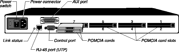
Note: Figure 2-1 shows two PCMCIA card modems inserted in slots 7 and 8. One Ascend
PCMCIA card ISDN adapter requires two slots.
Cables and connectors
Table 2-2 describes the cables and connectors used for the MAX 800 ports.
What is on the front panel?
The front panel contains 34 indicator lights. Thirty-two lights, labeled Modem Status, correspond to the eight PCMCIA card slots on the back panel. The other two lights indicate power and network traffic.
Figure 2-2. MAX 800 front panel
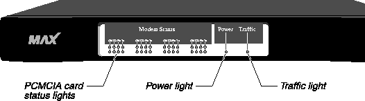
Once you understand what the MAX 800 status-indicator lights represent, why they flash, and when they should not be flashing, you can interpret the status of your MAX 800 and its PCMCIA cards. Figure 2-3 shows the location of the lights.
For information about how to interpret lights that do not operate as described in this section, see to Appendix B, Troubleshooting.
Figure 2-3. MAX 800 indicator lights

Power light
The green Power light indicates when the unit has been turned on and is receiving power.
Traffic light
The yellow Traffic light blinks to indicate that the MAX 800 has been properly installed and is transmitting and receiving data across the network.
Indicator light activity for PCMCIA cards
Each of the eight modem slots on the MAX 800 unit's back panel has four corresponding lights on the front panel. They are:
- ON-Power (green)
- CD-Carrier Detect (red)
- Rx-Receive data (yellow)
- Tx-Transmit data (yellow)
These four lights provide status information corresponding to each of the eight PCMCIA cards optionally plugged into the MAX 800. (See Figure 2-3.)
The activity of the lights and how to interpret them differs depending on which type of card is in use. "Light activity for PCMCIA card modems" describes how to interpret the lights when a PCMCIA card modem is inserted in the corresponding slot. Light activity for Ascend PCMCIA card ISDN adapters explains how to interpret them when a PCMCIA card ISDN adapter is inserted in the corresponding slot.
Light activity for PCMCIA card modems
The following sections describe indicator light activity and interpretation when PCMCIA card modems are in use.
ON
Each of the ON indicator lights indicates whether the corresponding modem is connected correctly and/or recognized by the MAX 800. When this light is on, the modem is ready to receive data.
A flashing ON light means that the MAX 800 does not recognize the modem but is going to attempt to receive data through it anyway and interpret the data as Hayes-compatible modem commands. This happens only when the modem is not on the approved list or is malfunctioning. You can eject the questionable modem or let the MAX 800 attempt to receive data through it.
CD
A CD light turns on when an outside phone line connects to the corresponding modem. The light remains lit until the remote party disconnects from the line.
Rx
An RX light flashes when data is being received over the phone line through the associated modem.
Tx
A TX light flashes when data is being transmitted over the phone line through the associated modem.
Light activity for Ascend PCMCIA card ISDN adapters
The following sections describe indicator light activity and interpretation when PCMCIA card ISDN adapters are in use.
ON
When the ISDN adapter completes its startup diagnostic tests, the lower ON light is illuminated. The upper ON light illuminates after the PCMCIA card establishes network communication. (See Figure 2-3.)
Note: Establishment of network communication occurs only after you properly configure the
PCMCIA cards. If you are using NavisConnect to configure and manage your MAX 800, see
the NavisConnect User's Guide. If you are using the VT100 interface, see the Network
Configuration Guide for your MAX 800.
CD
A CD light (red) illuminates when a call is in progress. The top light illuminates when a B1 channel call is in progress. The bottom light illuminates when a B2 channel call is in progress.
Rx
An RX light flashes when data is being received over the phone line and through the associated PCMCIA card. The top light is for the B1 channel. The bottom light is for the B2 channel.
Tx
A TX light flashes when data is being transmitted over the phone line through the associated PCMCIA card. The top light is for the B1 channel. The bottom light is for the B2 channel.
Setting up the hardware
When you are ready to set up the MAX 800, gather the package contents and place the unit so that the back panel is facing you. Make sure the power switch is in the Off position (labeled 0). Then connect the appropriate cables to your PCMCIA-card modems or adapters, insert the cards, and position the unit for use (rack mounted or on a flat surface).
So that you can later configure the unit, you need to set up a controlling computer. You can either run NavisConnect on the same subnet to which you connect the MAX 800, or connect a VT100 terminal or terminal emulator to the MAX 800 control port.
Finally, connect the MAX 800 to your network, plug in the power cord, and switch the unit on.
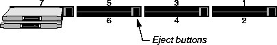
Inserting the PCMCIA cards
The MAX 800 can accommodate approved Type II PCMCIA-card modems and Ascend Type III PCMCIA card ISDN adapters. You can insert up to eight Type II PCMCIA card modems or up to four Ascend Type III PCMCIA card ISDN adapters. You can place both types of card in a single MAX 800. However, the ISDN adapter PCMCIA cards each take up two PCMCIA card slots.
PCMCIA cards are hot-swappable, which means you can insert and eject the cards when the MAX 800 power is on without damaging the cards or the MAX 800. After swapping cards, restart the MAX 800.
Note: Ascend BRI cards are supported only in MAX 200Plus or MAX 800 units.
To insert a PCMCIA card into the slot:
- Plug the appropriate cable into each PCMCIA card. Use only the cable supplied with each PCMCIA-card modem or adapter or that recommended by the card's manufacturer.
- Connect each PCMCIA card to the MAX 800 by pushing the card into a slot on the back panel. Ascend recommends that you begin with slot number one and continue in numerical order. You can, however, use any combination of the eight slots on the back of the MAX 800. Figure 2-4 shows where the slots are located.
Most PCMCIA cards have an arrow showing the direction in which to insert them. The slots are grouped in twos. To avoid improper positioning, you must hold the card horizontally when inserting it into a slot.
Figure 2-4. PCMCIA-card modems in slots
Note: You should use PCMCIA-card modems with internal RJ-11 adapters (such as
XJACK) only in the upper slots. In this way, the telephone cable plugged into the modem
does not interfere with modems in the lower slots.
When a PCMCIA card is connected firmly, the eject button associated with it pops out.
- Use the cable recommended by your PCMCIA card manufacturer to connect the card to the telephone wall jack.
See the manufacturer's documentation before connecting to the telephone system.
- Check your connection. When a PCMCIA card is connected firmly, the eject button associated with it pops out. When the PCMCIA card has been installed correctly, the green light labeled ON is illuminated.
You can remove PCMCIA cards from the MAX 800 by pushing the eject button to the right of the card you want to remove.
Note: Two modem slots are housed in such a way that they touch each other. Be aware that by
pushing one button you might inadvertently eject both modems. To avoid this happening, you
can use a finger to hold the modem you do not want to eject in place while pressing the button.
Positioning the MAX 800
You can either rack mount the MAX 800 in a wiring closet or place it on a flat surface.
Rack-mounting the MAX 800
The MAX 800 package includes mounting brackets for attaching the unit to your equipment rack. You can attach the rack-mounting ears to either the front or back of the MAX 800 unit. Proceed as follows:
- Place the MAX 800 upside down on a flat surface, with the front panel facing you.
- Align the screw holes on a rack-mount bracket with the screw holes on the MAX 800. You can position the bracket in either direction to accommodate your particular equipment rack.
- Using a Phillips screwdriver, attach the three screws included with your kit.
- Follow steps 2 and 3 to attach the other bracket.
- Follow the equipment rack manufacturer's instructions to attach the MAX 800 to your rack.
Placing the MAX 800 on a flat surface
If you place the MAX 800 on a table, make sure you choose a location where air can circulate. Make sure that none of the unit's side air vents are obstructed.
Setting up a controlling computer
To make sure that the MAX 800 is functioning properly, you have to configure some basic settings after you complete the installation. At the same time, you should configure basic security settings to prevent users from reconfiguring the unit. The MAX Companion CD-ROM you received with the MAX 800 includes NavisConnect, which simplifies configuration tasks.
To use NavisConnect, you must install it on a workstation running Windows 3.1, Windows 95 or 98, or Windows NT4.0 on the same subnet to which you connect the MAX 800. The workstation should also have a Web browser installed, so that you can access online help for NavisConnect. To install NavisConnect, place the disk in the CD-ROM drive and use the Windows run function to execute NavisConnect 1.0.exe.
Alternatively, you can connect a VT100 terminal, or a computer with VT100-emulation software, to the MAX 800 control port. (Most communications programs include VT100 emulation.) This method is recommended only for administrators with experience in configuring Ascend products. To connect the terminal or computer to the MAX 800, use the supplied straight-through cable to connect the MAX 800 control port to a serial port on the terminal or computer. If using a terminal emulator, be sure to specify the serial port to which you have connected the MAX 800, and set the communications parameters as follows:
- VT100 emulation
- 9600 bps
- 8 data bits
- No parity
- 1 stop bit
- Direct connect
After you have assigned an IP address to the MAX 800, you can also use a Telnet session for configuration. A Telnet session provides an identical VT100-configuration interface to that provided through the control port.
Connecting the MAX 800 to your network
You can connect the MAX 800 directly to your 10Base-5 (thick) or 10Base-T (twisted-pair) Ethernet cabling system. Each MAX 800 can support only one type of Ethernet connection at a time. The MAX 800 automatically senses the type of Ethernet connection.
To install the MAX 800 on your network, follow the instructions for your cabling system.
Connecting the MAX 800 to a 10Base-T Ethernet network
To connect the MAX 800 to a 10Base-T network:
- Plug the RJ-45 plug at one end of the 10Base-T (twisted pair) cable into the UTP port on the back panel of the MAX 800.
- Plug the RJ-45 plug at the other end of the 10Base-T cable into the RJ-45 wall jack to access the network hub.
Connecting the MAX 800 to a 10Base-5 Ethernet network
To connect the MAX 800 to 10Base-5 network:
- Open the slide mechanism on the 15-pin D-subminiature connector on the 10Base-5 coaxial cable. Insert the connector into the MAX 800 unit's AUI port. Push the slide mechanism to secure the connection.
- Plug the 15-pin connector at the other end of the cable into the 10Base-5 transceiver.
Where to go next?
The next chapter describes how to power on the MAX 800 and set basic security settings to ensure that unauthorized users cannot tamper with the MAX 800 unit's operational settings.
techpubs@ascend.com
Copyright © 1998, Ascend Communications, Inc. All rights
reserved.